- 您現(xiàn)在的位置:買賣IC網(wǎng) > PDF目錄374693 > SABC161RI-L16M (SIEMENS AG) 16-Bit CMOS Single-Chip Microcontroller PDF資料下載
參數(shù)資料
| 型號: | SABC161RI-L16M |
| 廠商: | SIEMENS AG |
| 英文描述: | 16-Bit CMOS Single-Chip Microcontroller |
| 中文描述: | 16位CMOS單芯片微控制器 |
| 文件頁數(shù): | 9/60頁 |
| 文件大?。?/td> | 614K |
| 代理商: | SABC161RI-L16M |
第1頁第2頁第3頁第4頁第5頁第6頁第7頁第8頁當(dāng)前第9頁第10頁第11頁第12頁第13頁第14頁第15頁第16頁第17頁第18頁第19頁第20頁第21頁第22頁第23頁第24頁第25頁第26頁第27頁第28頁第29頁第30頁第31頁第32頁第33頁第34頁第35頁第36頁第37頁第38頁第39頁第40頁第41頁第42頁第43頁第44頁第45頁第46頁第47頁第48頁第49頁第50頁第51頁第52頁第53頁第54頁第55頁第56頁第57頁第58頁第59頁第60頁
Semiconductor Group
9
1998-05-01
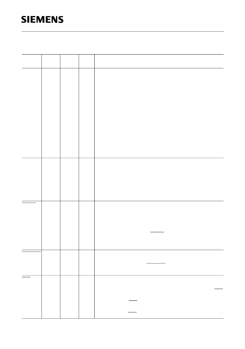
C161RI
PORT0:
P0L.0 –
P0L.7,
P0H.0 -
P0H.7
38 –
45,
48 –
55
40 –
47,
50 –
57
I/O
PORT0 consists of the two 8-bit bidirectional I/O ports P0L
and P0H. It is bit-wise programmable for input or output via
direction bits. For a pin configured as input, the output driver
is put into high-impedance state.
In case of external bus configurations, PORT0 serves as the
address (A) and address/data (AD) bus in multiplexed bus
modes and as the data (D) bus in demultiplexed bus modes.
Demultiplexed bus modes:
Data Path Width:
8-bit
P0L.0 – P0L.7:
D0 – D7
P0H.0 – P0H.7:
I/O
Multiplexed bus modes:
Data Path Width:
8-bit
P0L.0 – P0L.7:
AD0 – AD7
P0H.0 – P0H.7:
A8 - A15
16-bit
D0 - D7
D8 - D15
16-bit
AD0 - AD7
AD8 - AD15
PORT1:
P1L.0 –
P1L.7,
P1H.0 -
P1H.7
56 –
63,
66 –
73
58 -
65,
68 -
75
I/O
PORT1 consists of the two 8-bit bidirectional I/O ports P1L
and P1H. It is bit-wise programmable for input or output via
direction bits. For a pin configured as input, the output driver
is put into high-impedance state. PORT1 is used as the 16-
bit address bus (A) in demultiplexed bus modes and also
after switching from a demultiplexed bus mode to a
multiplexed bus mode.
RSTIN
76
78
I
Reset Input with Schmitt-Trigger characteristics. A low level
at this pin for a specified duration while the oscillator is
running resets the C161RI. An internal pullup resistor permits
power-on reset using only a capacitor connected to
V
SS
.
In bidirectional reset mode (enabled by setting bit BDRSTEN
in register SYSCON) the RSTIN line is internally pulled low
for the duration of the internal reset sequence upon a
software reset, a WDT reset and a hardware reset.
1)
RSTOUT 77
79
O
Internal Reset Indication Output. This pin is set to a low level
when the part is executing either a hardware-, a software- or
a watchdog timer reset. RSTOUT remains low until the EINIT
(end of initialization) instruction is executed.
NMI
78
80
I
Non-Maskable Interrupt Input. A high to low transition at this
pin causes the CPU to vector to the NMI trap routine. When
the PWRDN (power down) instruction is executed, the NMI
pin must be low in order to force the C161RI to go into power
down mode. If NMI is high, when PWRDN is executed, the
part will continue to run in normal mode.
If not used, pin NMI should be pulled high externally.
Pin Definitions and Functions
(cont’d)
Symbol
Pin No.
TQFP
Pin No.
MQFP
Input
Outp
Function
相關(guān)PDF資料 |
PDF描述 |
|---|---|
| SAC | Low Capacitance Transient Voltage Suppressor Diodes |
| SAE0530 | PROGRAMMABLE TIMER |
| SAE0531 | PROGRAMMABLE TIMER |
| SAE0532 | PROGRAMMABLE TIMER |
| SAE0532G | PROGRAMMABLE TIMER |
相關(guān)代理商/技術(shù)參數(shù) |
參數(shù)描述 |
|---|---|
| SAB-C-161S-L25M | 制造商:Rochester Electronics LLC 功能描述: 制造商:Infineon Technologies AG 功能描述: |
| SAB-C161S-L25M | 制造商:INFINEON 制造商全稱:Infineon Technologies AG 功能描述:16-Bit Single-Chip Microcontroller |
| SAB-C161S-L25M AA | 功能描述:16位微控制器 - MCU 16-Bit Single-Chip 5V 25MHz ROM less RoHS:否 制造商:Texas Instruments 核心:RISC 處理器系列:MSP430FR572x 數(shù)據(jù)總線寬度:16 bit 最大時(shí)鐘頻率:24 MHz 程序存儲(chǔ)器大小:8 KB 數(shù)據(jù) RAM 大小:1 KB 片上 ADC:Yes 工作電源電壓:2 V to 3.6 V 工作溫度范圍:- 40 C to + 85 C 封裝 / 箱體:VQFN-40 安裝風(fēng)格:SMD/SMT |
| SABC161SL25MAAXT | 制造商:Infineon Technologies AG 功能描述:MCU 16-Bit C166 CISC/RISC ROMLess 5V 80-Pin MQFP |
| SAB-C161S-LM 3V | 制造商:Infineon Technologies AG 功能描述:16BIT MCU ROM/ROMLESS MQFP80 161 |
發(fā)布緊急采購,3分鐘左右您將得到回復(fù)。