- 您現(xiàn)在的位置:買賣IC網(wǎng) > PDF目錄372115 > SAA7335GP (NXP SEMICONDUCTORS) DSP for CD and DVD-ROM systems PDF資料下載
參數(shù)資料
| 型號(hào): | SAA7335GP |
| 廠商: | NXP SEMICONDUCTORS |
| 元件分類: | 消費(fèi)家電 |
| 英文描述: | DSP for CD and DVD-ROM systems |
| 中文描述: | SPECIALTY CONSUMER CIRCUIT, PQFP100 |
| 封裝: | 14 X 14 MM, 1.40 MM HEIGHT, PLASTIC, MS-026, SOT-407-1, LQFP-100 |
| 文件頁(yè)數(shù): | 18/36頁(yè) |
| 文件大小: | 196K |
| 代理商: | SAA7335GP |
第1頁(yè)第2頁(yè)第3頁(yè)第4頁(yè)第5頁(yè)第6頁(yè)第7頁(yè)第8頁(yè)第9頁(yè)第10頁(yè)第11頁(yè)第12頁(yè)第13頁(yè)第14頁(yè)第15頁(yè)第16頁(yè)第17頁(yè)當(dāng)前第18頁(yè)第19頁(yè)第20頁(yè)第21頁(yè)第22頁(yè)第23頁(yè)第24頁(yè)第25頁(yè)第26頁(yè)第27頁(yè)第28頁(yè)第29頁(yè)第30頁(yè)第31頁(yè)第32頁(yè)第33頁(yè)第34頁(yè)第35頁(yè)第36頁(yè)
1997 Aug 11
18
Philips Semiconductors
Preliminary specification
DSP for CD and DVD-ROM systems
SAA7335
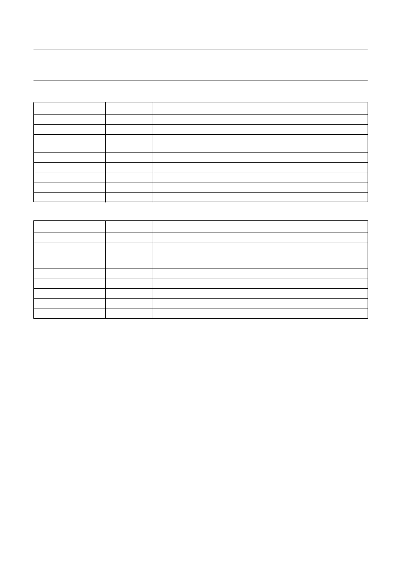
Table 4
EBU word format
Table 5
EBU channel status
WORD
BITS
FUNCTION
Sync
Auxiliary
Error flags
0 to 3
4 to 7
4
not used; normally zero
CFLG error and interpolation flags when bit 3 of EBU control register is set
to logic 1
first 4 bits not used (always zero)
valid = logic 0
used for subcode data (Q-to-W)
control bits and category code
even parity for bits 4 to 30
Audio sample
Validity flag
User data
Channel status
Parity bit
8 to 27
28
29
30
31
WORD
BITS
FUNCTION
Consumer/professional
Control
0
always zero
copied from bits 3 to 0 of register OUTPUT2, normally should be set to a
copy of CRC checked Q-channel control bits 0 to 3; bit 2 is logic 1 when
copy permitted; bit 3 is logic 1 when recording has pre-emphasis
always zero
CD; bit 8 = logic 1, all other bits = logic 0
always zero
set by OUTPUT2 control register bits 5 and 4; 00 = level II, 01 = level III
always zero
1 to 4
Reserved
Category code
Reserved
Clock accuracy
Remaining
5 to 7
8 to 15
16 to 27
28 to 29
30 to 191
Spindle motor control
The spindle motor speed is controlled by a fully integrated
digital servo. Address information from the internal
±
8 frame FIFO and disc speed information are used to
calculate the motor control output signals.
Several output modes are supported:
1.
Pulse density, 1-line,
2.
Pulse density, 2-line (true complement output) (cannot
be used with tachometer control)
3.
PWM output, 2-line.
The modes are selected via the motor output configuration
register.
P
ULSE DENSITY MODE
In the pulse density mode the motor output (pin MOTO1)
is the pulse density modulated motor output signal. A 50%
duty cycle corresponds with the motor not actuated, higher
duty cycles mean acceleration, lower mean braking.
In this mode, the MOTO2 signal is the inverse of the
MOTO1 signal. Both signals change state only on the
edges of a internal clock signal.
Possible application diagrams are shown in Fig.13.
PWM
MODE
, 2-
LINE
In the PWM mode the motor acceleration signal is put in
pulse-width modulation form on the MOTO1 output and
the motor braking signal is pulse-width modulated on the
MOTO2 output.
Figure 14 illustrates the PWM mode timing and Fig.15
illustrates a typical PWM mode application diagram.
相關(guān)PDF資料 |
PDF描述 |
|---|---|
| SAA7335 | DSP for CD and DVD-ROM systems(在CD和DVD-ROM應(yīng)用中的DSP) |
| SAA7341 | COMS Digital decoding IC for Compact Disc |
| SAA7341GP | COMS Digital decoding IC for Compact Disc |
| SAA7345 | Bitstream conversion ADC for digital audio systems |
| SAA7345GP | Bitstream conversion ADC for digital audio systems |
相關(guān)代理商/技術(shù)參數(shù) |
參數(shù)描述 |
|---|---|
| SAA7341 | 制造商:PHILIPS 制造商全稱:NXP Semiconductors 功能描述:COMS Digital decoding IC for Compact Disc |
| SAA7341GP | 制造商:PHILIPS 制造商全稱:NXP Semiconductors 功能描述:COMS Digital decoding IC for Compact Disc |
| SAA7345 | 制造商:PHILIPS 制造商全稱:NXP Semiconductors 功能描述:Bitstream conversion ADC for digital audio systems |
| SAA7345GP | 制造商:PHILIPS 制造商全稱:NXP Semiconductors 功能描述:Bitstream conversion ADC for digital audio systems |
| SAA7346 | 制造商:PHILIPS 制造商全稱:NXP Semiconductors 功能描述:Shock absorbing RAM addresser |
發(fā)布緊急采購(gòu),3分鐘左右您將得到回復(fù)。