- 您現(xiàn)在的位置:買賣IC網(wǎng) > PDF目錄98068 > S1C60L05D 4-BIT, MROM, 0.08 MHz, MICROCONTROLLER, UUC53 PDF資料下載
參數(shù)資料
| 型號(hào): | S1C60L05D |
| 元件分類: | 微控制器/微處理器 |
| 英文描述: | 4-BIT, MROM, 0.08 MHz, MICROCONTROLLER, UUC53 |
| 封裝: | DIE-53 |
| 文件頁數(shù): | 103/104頁 |
| 文件大?。?/td> | 697K |
| 代理商: | S1C60L05D |
第1頁第2頁第3頁第4頁第5頁第6頁第7頁第8頁第9頁第10頁第11頁第12頁第13頁第14頁第15頁第16頁第17頁第18頁第19頁第20頁第21頁第22頁第23頁第24頁第25頁第26頁第27頁第28頁第29頁第30頁第31頁第32頁第33頁第34頁第35頁第36頁第37頁第38頁第39頁第40頁第41頁第42頁第43頁第44頁第45頁第46頁第47頁第48頁第49頁第50頁第51頁第52頁第53頁第54頁第55頁第56頁第57頁第58頁第59頁第60頁第61頁第62頁第63頁第64頁第65頁第66頁第67頁第68頁第69頁第70頁第71頁第72頁第73頁第74頁第75頁第76頁第77頁第78頁第79頁第80頁第81頁第82頁第83頁第84頁第85頁第86頁第87頁第88頁第89頁第90頁第91頁第92頁第93頁第94頁第95頁第96頁第97頁第98頁第99頁第100頁第101頁第102頁當(dāng)前第103頁第104頁

90
EPSON
S1C60N05 TECHNICAL MANUAL
APPENDIX: TECHNICAL INFORMATION
Transistor ON resistance error when Thermistor 103AT measures
60°C
10
× 103
}
× 100 ≈ 1%
(10
× 103 + 100)
4 = { 1 -
3.217
× 103
}
× 100 ≈ 3%
(3.217
× 103 + 100)
As a result, the following errors occur by directly connecting the
transistor ON resistance:
1% at CR oscillation on the standard resistor
3% at CR oscillation on Thermistor
The transistor ON resistance effect is smaller if R1 and R2 are
larger. (See Equation
3 and 4.)
In the high temperature range, the R2 value becomes small and
4
becomes large. This causes precision degradation. Compensation
is needed to implement a user's required precision.
Example:
Error by floating
capacity
The floating capacity of the inside of an IC, board, lead of a sensor
and others may be an error factor. Floating capacity inside an IC
may be several pF and it may be ignored by increasing the capaci-
tor value.
Software error
In the software, it is normal to convert the counter value to an
actual temperature by a linear approximation. In this method, an
error may be caused by the linear approximation in the tempera-
ture measured range.
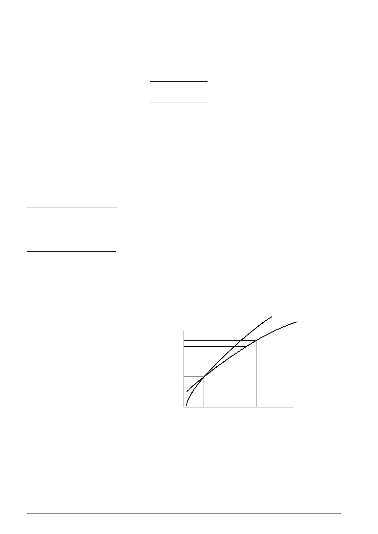
As shown in Figure B.4 below, if the temperature range measured
is 20°C to 30°C, the weight of 1 count differs between 20°C and
29°C.
Fig. B.4
30
(1)
(2)
Temperature (
°C)
Counts (times)
29
20
On the slope (1), the linear approximation coefficient in this seg-
ment for 1 count is large, and the slope (2) has a smaller coeffi-
cient.
For example, if this segment (20°C to 30°C) is calculated by the
same linear approximation coefficient, and if the 20°C is the
reference point, then, at 29°C, the linear approximation coefficient
becomes the largest and, at 29°C, the error is maximum.
The error may differ depending on the temperature measured by
the software, up counter initial value and Thermistor type.
相關(guān)PDF資料 |
PDF描述 |
|---|---|
| S1C60L13F | 4-BIT, MROM, 0.032768 MHz, MICROCONTROLLER, PQFP80 |
| S1C60L13D | 4-BIT, MROM, 0.032768 MHz, MICROCONTROLLER, UUC79 |
| S1C60A13F | 4-BIT, MROM, 1.2 MHz, MICROCONTROLLER, PQFP80 |
| S1C60L16F0A0100 | 4-BIT, MROM, 0.032768 MHz, MICROCONTROLLER, PQFP80 |
| S1C60N01F | 4-BIT, MROM, 0.08 MHz, MICROCONTROLLER, PQFP48 |
相關(guān)代理商/技術(shù)參數(shù) |
參數(shù)描述 |
|---|---|
| S1C60L08 | 制造商:EPSON 制造商全稱:EPSON 功能描述:4-bit Single Chip Microcomputer |
| S1C60L16 | 制造商:EPSON 制造商全稱:EPSON 功能描述:4-bit Single Chip Microcomputer |
| S1C60N05 | 制造商:EPSON 制造商全稱:EPSON 功能描述:4-bit Single Chip Microcomputer |
| S1C60N08 | 制造商:EPSON 制造商全稱:EPSON 功能描述:4-bit Single Chip Microcomputer |
| S1C60N16 | 制造商:EPSON 制造商全稱:EPSON 功能描述:4-bit Single Chip Microcomputer |
發(fā)布緊急采購(gòu),3分鐘左右您將得到回復(fù)。