- 您現(xiàn)在的位置:買賣IC網(wǎng) > PDF目錄374604 > RV4141 (Fairchild Semiconductor Corporation) Low Power Ground Fault Interrupter PDF資料下載
參數(shù)資料
| 型號: | RV4141 |
| 廠商: | Fairchild Semiconductor Corporation |
| 英文描述: | Low Power Ground Fault Interrupter |
| 中文描述: | 低功耗接地故障滅弧室 |
| 文件頁數(shù): | 5/8頁 |
| 文件大小: | 345K |
| 代理商: | RV4141 |
RV4141A
PRODUCT SPECIFICATION
REV. 1.0.1 7/8/03
5
R
fier is its maximum of 200 μV, the trip current error is
±5.6%.
SET
is 1 M
, R
SEC
is 45
and the V
OS
of the sense ampli-
The SCR anode is directly connected to a solenoid or relay
coil. It can be tripped only when its anode is more positive
than its cathode. It must have a high dV/dt rating to ensure
that line noise (generated by electrically noisy appliances)
does not falsely trigger it. Also the SCR must have a gate
drive requirement less than 200 μA. C3 is a noise filter that
prevents high frequency line pulses from triggering the SCR.
The relay solenoid used should have a response time of 3 ms
or less to meet the UL 943 timing requirement.
Sense Transformers and Cores
The sense and ground/neutral transformer cores are usually
fabricated using high permeability laminated steel rings.
Their single turn primary is created by passing the line and
neutral wires through the center of its core. The secondary is
usually from 200 to 1500 turns.
Magnetic Metals Corporation
1900 Hayes Ave.
Camden, NJ 08105
(856) 964-7842
Is a full-line suppliers of ring cores and transformers
designed specifically for GFCI and related applications.
Calculating The Values Of R
Determine the nominal ground fault trip current requirement.
This will be typically 5 mA in North America (117V AC)
and 22 mA in the UK and Europe (220V AC). Determine the
minimum delay time required to prevent nuisance tripping.
This will typically be 1 to 2 ms. The value of C2 required to
provide the desired delay time is:
SET
and C2
C2 = 6 x T
where:
C2 is in nF
T is the desired delay time in ms.
The value of R
rent specification is:
SET
to meet the nominal ground fault trip cur-
where:
R
SET
T is the time delay in ms
P is the period of the line frequency in ms
I
FAULT
is the desired ground fault trip current in mA RMS
N is the number of sense transformer secondary turns.
is in k
This formula assumes an ideal sense transformer is used.
The calculated value of R
SET
30% to when using a non-ideal transformer.
may have to be changed up to
R
SET
COS 180
N
×
I
FAULT
T P
(
)
-----------------------4.6
=
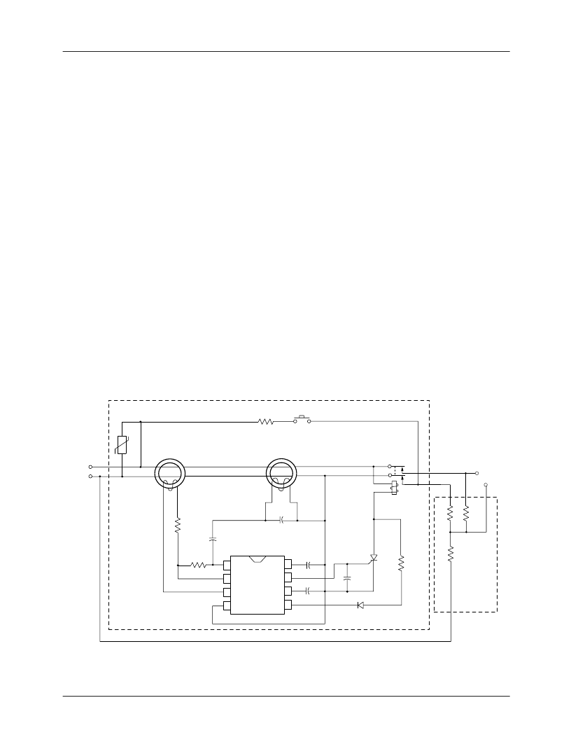
Figure 1. GFI Application Circuit
Mov
Line
Sense Transformer
1:1000
5 Ring Steel Core
Phase
Neutral
R
TEST
Press to
Test
Grounded Neutral
1:200
Normally Closed
Latching Contacts
Load
Fault
Resistance
Not Part of
Application
RV4141A
Solenoid
R
B
20K
R
N
0.4
R
G
1.6
R
LINE
24K
1W
Q1
TAG
X0103DA
C3
10 nF
C2
12 nF
C
F
+
1
μ
F 35V
C4
1000 pF
C1
10 nF
R
SET
1.1 Meg
R
IN
470
1
2
3
4
8
7
6
5
GFCI
Note:
1. Portions of this schematic are subject to U.S. patents 3,878,435 and Re. 30,678.
15K
65-4141A-03
1N4004
相關(guān)PDF資料 |
PDF描述 |
|---|---|
| RV4141A | Low Power Ground Fault Interrupter |
| RV4141AM | Low Power Ground Fault Interrupter |
| RV4141AN | Low Power Ground Fault Interrupter |
| RV4145 | Low Power Ground Fault Interrupter |
| RV4145A | Low Power Ground Fault Interrupter |
相關(guān)代理商/技術(shù)參數(shù) |
參數(shù)描述 |
|---|---|
| RV4141A | 制造商:FAIRCHILD 制造商全稱:Fairchild Semiconductor 功能描述:Low Power Ground Fault Interrupter |
| RV4141A_05 | 制造商:FAIRCHILD 制造商全稱:Fairchild Semiconductor 功能描述:Low Power Ground Fault Interrupter |
| RV4141A_11 | 制造商:FAIRCHILD 制造商全稱:Fairchild Semiconductor 功能描述:Low-Power, Ground-Fault Interrupter |
| RV4141AM | 功能描述:其他電源管理 LOW POWER GFI RoHS:否 制造商:Texas Instruments 輸出電壓范圍: 輸出電流:4 mA 輸入電壓范圍:3 V to 3.6 V 輸入電流: 功率耗散: 工作溫度范圍:- 40 C to + 110 C 安裝風(fēng)格:SMD/SMT 封裝 / 箱體:VQFN-48 封裝:Reel |
| RV4141AMT | 功能描述:其他電源管理 LOW POWER GFI RoHS:否 制造商:Texas Instruments 輸出電壓范圍: 輸出電流:4 mA 輸入電壓范圍:3 V to 3.6 V 輸入電流: 功率耗散: 工作溫度范圍:- 40 C to + 110 C 安裝風(fēng)格:SMD/SMT 封裝 / 箱體:VQFN-48 封裝:Reel |
發(fā)布緊急采購,3分鐘左右您將得到回復(fù)。