- 您現(xiàn)在的位置:買賣IC網(wǎng) > PDF目錄66142 > RO3101D (RF MONOLITHICS INC) 1-PORT SAW RESONATOR, 433.92 MHz PDF資料下載
參數(shù)資料
| 型號: | RO3101D |
| 廠商: | RF MONOLITHICS INC |
| 元件分類: | SAW諧振器 |
| 英文描述: | 1-PORT SAW RESONATOR, 433.92 MHz |
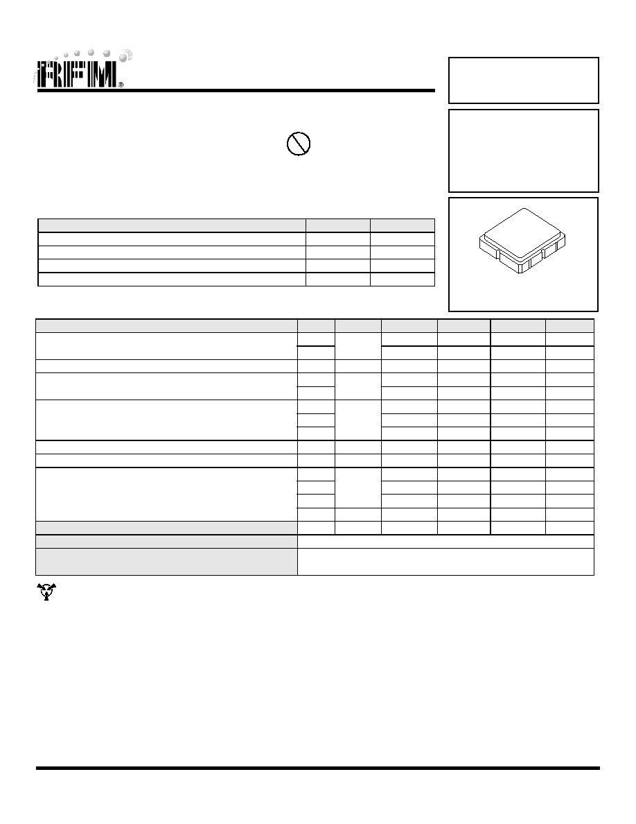
| 封裝: | ROHS COMPLIANT, CERAMIC, CASE SM3838-6, 6 PIN |
| 文件頁數(shù): | 1/2頁 |
| 文件大小: | 93K |
| 代理商: | RO3101D |
www.RFM.com
E-mail: info@rfm.com
Page 1 of 2
2008 by RF Monolithics, Inc.
RO3101D - 3/26/08
CAUTION: Electrostatic Sensitive Device. Observe precautions for handling.
Notes:
Electrical Characteristics
Characteristic
Sym
Notes
Minimum
Typical
Maximum
Units
Center Frequency (+25 °C)
Absolute Frequency
fC
2,3,4,5
433.845
433.995
MHz
Tolerance from 433.920 MHz
ΔfC
±75
kHz
Insertion Loss
IL
2,5,6
1.3
2.5
dB
Quality Factor
Unloaded Q
QU
5,6,7
8900
50
Ω Loaded Q
QL
1250
Temperature Stability
Turnover Temperature
TO
6,7,8
10
25
40
°C
Turnover Frequency
fO
fC
Frequency Temperature Coefficient
FTC
0.032
ppm/°C2
Frequency Aging
Absolute Value during the First Year
|fA|
1
≤10
ppm/yr
DC Insulation Resistance between Any Two Terminals
5
1.0
M
Ω
RF Equivalent RLC Model
Motional Resistance
RM
5, 7, 9
16.4
Ω
Motional Inductance
LM
53.1
H
Motional Capacitance
CM
2.5
fF
Shunt Static Capacitance
CO
5, 6, 9
2.4
pF
Test Fixture Shunt Inductance
LTEST
2, 7
56.7
nH
Lid Symbolization (in addition to Lot and/or Date Codes)
702 // YWWS
Standard Reel Quantity
Reel Size 7 Inch
500 Pieces/Reel
Reel Size 13 Inch
3000 Pieces/Reel
Ideal for European 433.92 MHz Transmitters
Very Low Series Resistance
Quartz Stability
Complies with Directive 2002/95/EC (RoHS)
The RO3101D is a true one-port, surface-acoustic-wave (SAW) resonator in a surface-mount, ceramic case.
It provides reliable, fundamental-mode, quartz frequency stabilization of fixed-frequency transmitters
operating at 433.92 MHz. This SAW is designed specifically for remote-control and wireless security
transmitters operating in Europe under ETSI I-ETS 300 220 and in Germany under FTZ 17 TR 2100.
Absolute Maximum Ratings
Rating
Value
Units
Input Power Level
0
dBm
DC voltage
12
VDC
Storage Temperature
-40 to +85
°C
Soldering Temperature (10 seconds / 5 cycles max.)
260
°C
433.92 MHz
SAW
Resonator
RO3101D
1.
Frequency aging is the change in fC with time and is specified at +65°C or
less. Aging may exceed the specification for prolonged temperatures
above +65°C. Typically, aging is greatest the first year after manufacture,
decreasing in subsequent years.
2.
The center frequency, fC, is measured at the minimum insertion loss point,
ILMIN, with the resonator in the 50 Ω test system (VSWR ≤ 1.2:1). The
shunt inductance, LTEST, is tuned for parallel resonance with CO at fC.
Typically, fOSCILLATOR or fTRANSMITTER is approximately equal to the
resonator fC.
3.
One or more of the following United States patents apply: 4,454,488 and
4,616,197.
4.
Typically, equipment utilizing this device requires emissions testing and
government approval, which is the responsibility of the equipment
manufacturer.
5.
Unless noted otherwise, case temperature TC = +25°C±2°C.
6.
The design, manufacturing process, and specifications of this device are
subject to change without notice.
7.
Derived mathematically from one or more of the following directly
measured parameters: fC, IL, 3 dB bandwidth, fC versus TC, and CO.
8.
Turnover temperature, TO, is the temperature of maximum (or turnover)
frequency, fO. The nominal frequency at any case temperature, TC, may be
calculated from: f = fO [1 - FTC (TO -TC)
2]. Typically oscillator T
O is
approximately equal to the specified resonator TO.
9.
This equivalent RLC model approximates resonator performance near the
resonant frequency and is provided for reference only. The capacitance CO
is the static (nonmotional) capacitance between the two terminals
measured at low frequency (10 MHz) with a capacitance meter. The
measurement includes parasitic capacitance with "NC” pads unconnected.
Case parasitic capacitance is approximately 0.05 pF. Transducer parallel
capacitance can by calculated as: CP ≈ CO -0.05pF.
SM3838-6 Case
3.8 X 3.8
Pb
相關(guān)PDF資料 |
PDF描述 |
|---|---|
| RO3101E | 1-PORT SAW RESONATOR, 433.92 MHz |
| RO3103D | 1-PORT SAW RESONATOR, 418 MHz |
| RO3103E | 1-PORT SAW RESONATOR, 418 MHz |
| RO3104 | 1-PORT SAW RESONATOR, 303.825 MHz |
| RO3112 | 1-PORT SAW RESONATOR, 433.42 MHz |
相關(guān)代理商/技術(shù)參數(shù) |
參數(shù)描述 |
|---|---|
| RO3101E | 功能描述:諧振器 433.92 MHz +/-75kHz Single Port RoHS:否 制造商:Murata 頻率:30 MHz 容差:25 PPM 系列:XRCGB 端接類型:SMD/SMT 工作溫度范圍:- 10 C to + 70 C 尺寸:1.6 mm W x 2 mm L x 0.65 mm H 封裝:Reel |
| RO3101E-1 | 功能描述:諧振器 433.92 MHz +/-50kHz Single Port RoHS:否 制造商:Murata 頻率:30 MHz 容差:25 PPM 系列:XRCGB 端接類型:SMD/SMT 工作溫度范圍:- 10 C to + 70 C 尺寸:1.6 mm W x 2 mm L x 0.65 mm H 封裝:Reel |
| RO3101E-11 | 功能描述:諧振器 433.92MHz BW 75KHz IL 1.4dB Typ. SAW RoHS:否 制造商:Murata 頻率:30 MHz 容差:25 PPM 系列:XRCGB 端接類型:SMD/SMT 工作溫度范圍:- 10 C to + 70 C 尺寸:1.6 mm W x 2 mm L x 0.65 mm H 封裝:Reel |
| RO3102 | 制造商:RFM 功能描述:IC,RESON,423.22MHZ,TH,3TO-39 - Rail/Tube |
| RO3102A | 制造商:RFM 功能描述:423.22 MHZ SAW RESONATOR - Tape and Reel 制造商:RF Monolithics (RFM) 功能描述:RO Series 5 x 3.5 mm 423.22 MHZ Single Port Saw Resonator Surface Mount |
發(fā)布緊急采購,3分鐘左右您將得到回復(fù)。