- 您現(xiàn)在的位置:買(mǎi)賣(mài)IC網(wǎng) > PDF目錄358352 > RF1211D (RF MONOLITHICS INC) 1 FUNCTIONS, 315 MHz, SAW FILTER PDF資料下載
參數(shù)資料
| 型號(hào): | RF1211D |
| 廠商: | RF MONOLITHICS INC |
| 元件分類(lèi): | 聲表面波濾波器 |
| 英文描述: | 1 FUNCTIONS, 315 MHz, SAW FILTER |
| 封裝: | ROHS COMPLIANT, CASE SM3838-8, 8 PIN |
| 文件頁(yè)數(shù): | 1/2頁(yè) |
| 文件大?。?/td> | 68K |
| 代理商: | RF1211D |
www.RFM.com
2008 by RF Monolithics, Inc.
E-mail: info@rfm.com
Page 1 of 2
RF1211D - 3/21/08
Electrical Characteristics
Characteristic
Sym
Notes
Minimu
m
Typical
Maximu
m
Units
Center Frequency at 25°C
Insertion Loss
Passband Ripple (Relative to IL
MIN
) Fc ±150kHz
3 dB Bandwidth
Rejection Attenuation: (relative to ILmin) 10 - 295 MHz
Absolute Frequency
f
c
1, 2, 3
314.85
315.00
1.6
315.15
2.5
MHz
dB
IL
MIN
1, 3
1, 3
0.7
1.2
dB
BW
3
1, 3
500
46
41
27
15
6
20
15
33
43
55
600
51
46
30
17
8
24
18
35
45
60
800
kHz
1, 3
dB
295 - 305 MHz
305 - 310 MHz
310 - 313 MHz
313 - 314 MHz
316.5 - 320 MHz
320 - 325 MHz
325 - 335 MHz
335 - 600 MHz
600 - 1000 MHz
Freq. Temp. Coefficient
Temperature
Frequency Aging
Impedance @ fc
FTC
lfAl
Z
IN
Z
OUT
0.032
≤
10
5.0
//2.2pf
9.3
//1.7pf
ppm/°C
2
ppm/yr
Absolute Value during the First Year
Input Z
IN
=R
IN
llC
IN
Output Z
OUT
=R
OUT
llC
OUT
5
1
Lid Symbolization (Y=year WW=week S=shift)
Standard Reel Quantity
476 // YWWS
Reel Size 7 Inch
Reel Size 13 Inch
9
500 Pieces/Reel
3000 Pieces/Reel
Ideal Front-End Filter for Domestic Wireless Receivers
Low-Loss, Coupled-Resonator Quartz Design
Simple External Impedance Matching
Complies with Directive 2002/95/EC (RoHS)
The RF1211D is a low-loss, compact, and economical surface-acoustic-wave (SAW) filter
designed to provide front-end selectivity in 315.0 MHz receivers. Receiver designs using this filter
include superhet with 10.7 MHz or 500 kHz IF, direct conversion and superregen. Typical
applications of these receivers are wireless remote-control and security devices (especially for
automotive keyless entry) operating in the USA under FCC Part 15, in Canada under RSS-210,
and in Italy
This coupled-resonator filter (CRF) uses selective null placement to provide suppression, typically
greater than 40 dB, of the LO and image spurious responses of superhet receivers with 10.7 MHz
IF. RFM’s advanced SAW design and fabrication technology is utilized to achieve high
performance and very low loss with simple external impedance matching.
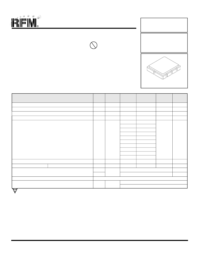
315.0 MHz
SAW Filter
RF1211D
SM3838-8 Case
3.8 x 3.8
CAUTION: Electrostatic Sensitive Device. Observe precautions for handling.
Notes:
1.
Unless noted otherwise, all measurements are made with the filter installed in the specified test fixture which is connected to a 50
test system with
VSWR
≤
1.2:1. The test fixture L and C are adjusted for minimum insertion loss at the filter center frequency, f
c
. Note that insertion loss and band-
width and passband shape are dependent on the impedance matching component values and quality.
2.
The frequency f
c
is defined as the midpoint between the 3dB frequencies.
3.
Where noted specifications apply over the entire specified operating temperature range of -40°C to +90°C.
4.
The turnover temperature, T
O
, is the temperature of maximum (or turnover) frequency, f
o
. The nominal frequency at any case temperature, T
c
, may
be calculated from: f = f
o
[1 - FTC (T
o
- T
c
)
2
].
5.
Frequency aging is the change in fc with time and is specified at +65°C or less. Aging may exceed the specification for prolonged temperatures
above +65°C. Typically, aging is greatest the first year after manufacture, decreasing significantly in subsequent years.
6.
The design, manufacturing process, and specifications of this device are subject to change.
7.
One or more of the following U.S. Patents apply: 4,54,488, 4,616,197, and others pending.
8.
All equipment designs utilizing this product must be approved by the appropriate government agency prior to manufacture or sale.
9.
Tape and Reel Standard Per ANSI / EIA 481.
Pb
相關(guān)PDF資料 |
PDF描述 |
|---|---|
| RF1283 | 1 FUNCTIONS, 433.92 MHz, SAW FILTER |
| RF3171D | 1 FUNCTIONS, 418 MHz, SAW FILTER |
| RF3501E | 1 FUNCTIONS, 866.1 MHz, SAW FILTER |
| RF6T-T4RP1-T4RP1-0100 | INTERCONNECTION DEVICE |
| RFBPF3225151G9-X | 2450 MHz, CERAMIC BPF |
相關(guān)代理商/技術(shù)參數(shù) |
參數(shù)描述 |
|---|---|
| RF1212-000 | 制造商:TE Connectivity 功能描述:SURGE PROTECTOR 220V SMA 50A |
| RF-1212D | 制造商:RECOM 制造商全稱(chēng):Recom International Power 功能描述:ECONOLINE - DC/DC - CONVERTER |
| RF-1212DH | 制造商:RECOM 制造商全稱(chēng):Recom International Power 功能描述:ECONOLINE - DC/DC - CONVERTER |
| RF-1212S | 制造商:RECOM 制造商全稱(chēng):Recom International Power 功能描述:ECONOLINE - DC/DC - CONVERTER |
| RF-1212SH | 制造商:RECOM 制造商全稱(chēng):Recom International Power 功能描述:ECONOLINE - DC/DC - CONVERTER |
發(fā)布緊急采購(gòu),3分鐘左右您將得到回復(fù)。