- 您現(xiàn)在的位置:買賣IC網(wǎng) > PDF目錄374580 > REF191FS (ANALOG DEVICES INC) Precision Micropower, Low Dropout, Voltage References PDF資料下載
參數(shù)資料
| 型號: | REF191FS |
| 廠商: | ANALOG DEVICES INC |
| 元件分類: | 基準電壓源/電流源 |
| 英文描述: | Precision Micropower, Low Dropout, Voltage References |
| 中文描述: | 1-OUTPUT THREE TERM VOLTAGE REFERENCE, 2.048 V, PDSO8 |
| 封裝: | SOIC-8 |
| 文件頁數(shù): | 14/23頁 |
| 文件大?。?/td> | 238K |
| 代理商: | REF191FS |
REF19x Series
WAFER TEST LIMITS
–14–
REV. D
Parameter
Symbol
Condition
Limits
Units
INITIAL ACCURACY
REF191
REF192
REF193
REF194
REF195
REF196
REF198
V
O
2.043/2.053
2.495/2.505
2.990/3.010
4.495/4.505
4.995/5.005
3.290/3.310
4.091/4.101
V
V
V
V
V
V
V
LINE REGULATION
V
O
/
V
IN
V
O
/
I
LOAD
(V
O
+ 0.5 V) < V
IN
< 15 V, I
OUT
= 0 mA
0 mA < I
LOAD
< 30 mA, V
IN
= (V
O
+ 1.3 V)
15
ppm/V
LOAD REGULATION
15
ppm/mA
DROPOUT VOLTAGE
V
O
– V+
I
LOAD
= 10 mA
I
LOAD
= 30 mA
1.25
1.55
V
V
SLEEP MODE INPUT
Logic Input High
Logic Input Low
V
IH
V
IL
V
IN
= 15 V
2.4
0.8
V
V
μ
A
μ
A
SUPPLY CURRENT
Sleep Mode
No Load
No Load
45
15
NOTE
For proper operation, a 1
μ
F capacitor is required between the output pins and the GND pin of the REF19x. Electrical tests and wafer probe to the limits shown. Due
to variations in assembly methods and normal yield loss, yield after packaging is not guaranteed for standard product dice. Consult factory to negotiate specifications
based on dice lot qualifications through sample lot assembly and testing.
ABSOLUTE MAXIMUM RATINGS
1
Supply Voltage . . . . . . . . . . . . . . . . . . . . . . . . . . –0.3 V, +18 V
Output to GND . . . . . . . . . . . . . . . . . . . . . . –0.3 V, V
S
+ 0.3 V
Output to GND Short-Circuit Duration . . . . . . . . . . Indefinite
Storage Temperature Range
P, S Package . . . . . . . . . . . . . . . . . . . . . . . . –65
°
C to +150
°
C
Operating Temperature Range
REF19x . . . . . . . . . . . . . . . . . . . . . . . . . . . .–40
°
C to +85
°
C
Junction Temperature Range
P, S Package . . . . . . . . . . . . . . . . . . . . . . . –65
°
C to +150
°
C
Lead Temperature Range (Soldering 60 sec) . . . . . . . . +300
°
C
Package Type
u
JA2
u
JC
Units
°
C/W
°
C/W
°
C/W
8-Lead Plastic DIP (P)
8-Lead SOIC (S)
8-Lead TSSOP
103
158
240
43
43
43
NOTES
1
Absolute maximum rating applies to both DICE and packaged parts, unless
otherwise noted.
2
θ
JA
is specified for worst case conditions, i.e.,
θ
JA
is specified for device in socket for
P-DIP, and
θ
JA
is specified for device soldered in circuit board for SOIC package.
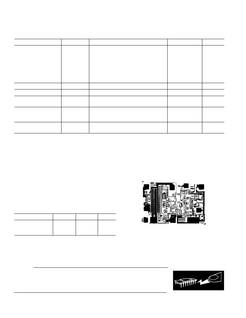
DICE CHARACTERISTICS
OUTPUT
6
OUTPUT
6
4
GND
3
SLEEP
2
V+
REF19x Die Size 0.041
×
0.057 Inch, 2,337 Sq. Mils
Substrate Is Connected to V+, Number of Transistors:
Bipolar 25, MOSFET4. Process: CBCMOS1
(@ I
LOAD
= 0 mA, T
A
= +25
°
C unless otherwise noted)
CAUTION
ESD (electrostatic discharge) sensitive device. Electrostatic charges as high as 4000 V readily
accumulate on the human body and test equipment and can discharge without detection.
Although the REF19x features proprietary ESD protection circuitry, permanent damage may
occur on devices subjected to high energy electrostatic discharges. Therefore, proper ESD
precautions are recommended to avoid performance degradation or loss of functionality.
WARNING!
ESD SENSITIVE DEVICE
相關(guān)PDF資料 |
PDF描述 |
|---|---|
| REF191GRU | Precision Micropower, Low Dropout, Voltage References |
| REF194 | Precision Micropower, Low Dropout, Voltage References |
| REF194ES | Precision Micropower, Low Dropout, Voltage References |
| REF194FS | Precision Micropower, Low Dropout, Voltage References |
| REF195 | Precision Micropower, Low Dropout, Voltage References |
相關(guān)代理商/技術(shù)參數(shù) |
參數(shù)描述 |
|---|---|
| REF191FS3 | 制造商:未知廠家 制造商全稱:未知廠家 功能描述:REF19x Series: Precision Micropower. Low Dropout. Low Voltage References Data Sheet (Rev. E. 1/03) |
| REF191GBC | 制造商:AD 制造商全稱:Analog Devices 功能描述:Precision Micropower, Low Dropout, Voltage References |
| REF191GP | 制造商:Analog Devices 功能描述:V-Ref Precision 2.048V 30mA 8-Pin PDIP Tube 制造商:Rochester Electronics LLC 功能描述:PRECISION MICROPOWER VOLTAGE REFERENCES - Bulk |
| REF191GPZ | 制造商:Analog Devices 功能描述:V-Ref Precision 2.048V 30mA 8-Pin PDIP Tube |
| REF191GRU | 制造商:AD 制造商全稱:Analog Devices 功能描述:Precision Micropower, Low Dropout, Voltage References |
發(fā)布緊急采購,3分鐘左右您將得到回復(fù)。