- 您現(xiàn)在的位置:買賣IC網(wǎng) > PDF目錄373225 > R29771SM PDF資料下載
參數(shù)資料
| 型號: | R29771SM |
| 文件頁數(shù): | 25/29頁 |
| 文件大小: | 188K |
| 代理商: | R29771SM |
第1頁第2頁第3頁第4頁第5頁第6頁第7頁第8頁第9頁第10頁第11頁第12頁第13頁第14頁第15頁第16頁第17頁第18頁第19頁第20頁第21頁第22頁第23頁第24頁當前第25頁第26頁第27頁第28頁第29頁
R296XX/R297XX
PRODUCT SPECIFICATION
24
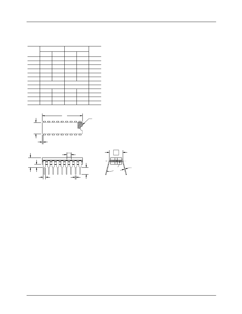
Mechanical Dimensions
(continued)
18 Lead Ceramic Dual Inline Package (CerDIP)
8. All leads - Increase maximum limit by .003(.08mm) measured at the center of the flat,
when lead finish is applied.
when " " is 90
.
7. "eA" shall be measured at the center of the lead bends or at the centerline of the leads
6. Applies to all four corner's (leads number 1, 8, 9, and 18).
pins 1 and 18.
±
.010 (.25mm) of its exact longitudinal position relative to
shall be located within
4. This dimension allows for off-center lid, meniscus and glass overrun.
3. Dimension "Q" shall be measured from the seating plane to the base plane.
one. The manufacturer's identification shall not be used as pin one identification mark.
2. The minimum limit for dimension "b2" may be .023(.58mm) for leads number 1, 8, 9
and 18 only.
1. Index area: a notch or a pin one identification mark shall be located adjacent to pin
Notes:
9. Sixteen spaces.
D
b2
e
b1
E
Q
A
L
s1
c1
eA
a
Note 1
A
b1
b2
c1
D
—
.014
.045
.008
—
.200
.023
.065
.015
.960
—
.36
1.14
.20
—
5.08
.58
1.65
.38
24.38
Symbol
Inches
Min.
Max.
Min.
Max.
Millimeters
Notes
E
e
eA
.220
.310
5.59
7.87
.100 BSC
.300 BSC
2.54 BSC
7.62 BSC
L
Q
s1
.125
.015
.005
90
.200
.070
—
105
3.18
.38
.13
90
5.08
1.78
—
105
3
6
8
4
4
8
2, 8
5, 9
7
a
相關PDF資料 |
PDF描述 |
|---|---|
| R29771SMS | |
| R29773 | |
| R29791 | |
| R29793 | |
| R29771LM | x8 PROM |
相關代理商/技術參數(shù) |
參數(shù)描述 |
|---|---|
| R29771SM/883B | 制造商:未知廠家 制造商全稱:未知廠家 功能描述: |
| R29771SMS | 制造商:未知廠家 制造商全稱:未知廠家 功能描述: |
| R29773 | 制造商:未知廠家 制造商全稱:未知廠家 功能描述: |
| R29773DM | 制造商:未知廠家 制造商全稱:未知廠家 功能描述:x8 PROM |
| R29773DMS | 制造商:未知廠家 制造商全稱:未知廠家 功能描述:x8 PROM |
發(fā)布緊急采購,3分鐘左右您將得到回復。