- 您現(xiàn)在的位置:買賣IC網(wǎng) > PDF目錄2016 > QPO-2LZ-01 (Vicor Corporation)IC INTERFACE FILTER PDF資料下載
參數(shù)資料
| 型號(hào): | QPO-2LZ-01 |
| 廠商: | Vicor Corporation |
| 文件頁(yè)數(shù): | 10/11頁(yè) |
| 文件大小: | 0K |
| 描述: | IC INTERFACE FILTER |
| 標(biāo)準(zhǔn)包裝: | 20 |
| 系列: | Picor®, QUIETPOWER® |
| 其它名稱: | 1102-1094-5 |
Picor Corporation www.picorpower.com
QPO-2 Data Sheet Rev. 1.6 Page 8 of 11
when using switching power supplies that have decreasing
ripple with increasing load current, like Vicor converters.
Figure 8 shows the headroom voltage vs. load with
different headroom resistors with RSA =8.2 k.
The slope adjust feature can be effectively disabled,
providing relatively constant headroom versus load, by
using an RSA of 100k. The user can optimize performance
based on the expected variation in load current and the
desired power dissipation range. The formula below
should be used to calculate the RSA value for the desired
headroom versus current slope. If the peak detector is
enabled, the peak of the ripple will be added back to the
headroom at a given load condition.
where: IOUT = Maximum load current change,
VHR = Change in headroom desired over
the load range,
RSA = Slope adjust resistor value,
Example: For a 5 A maximum load and a 150mV reduction
in headroom.
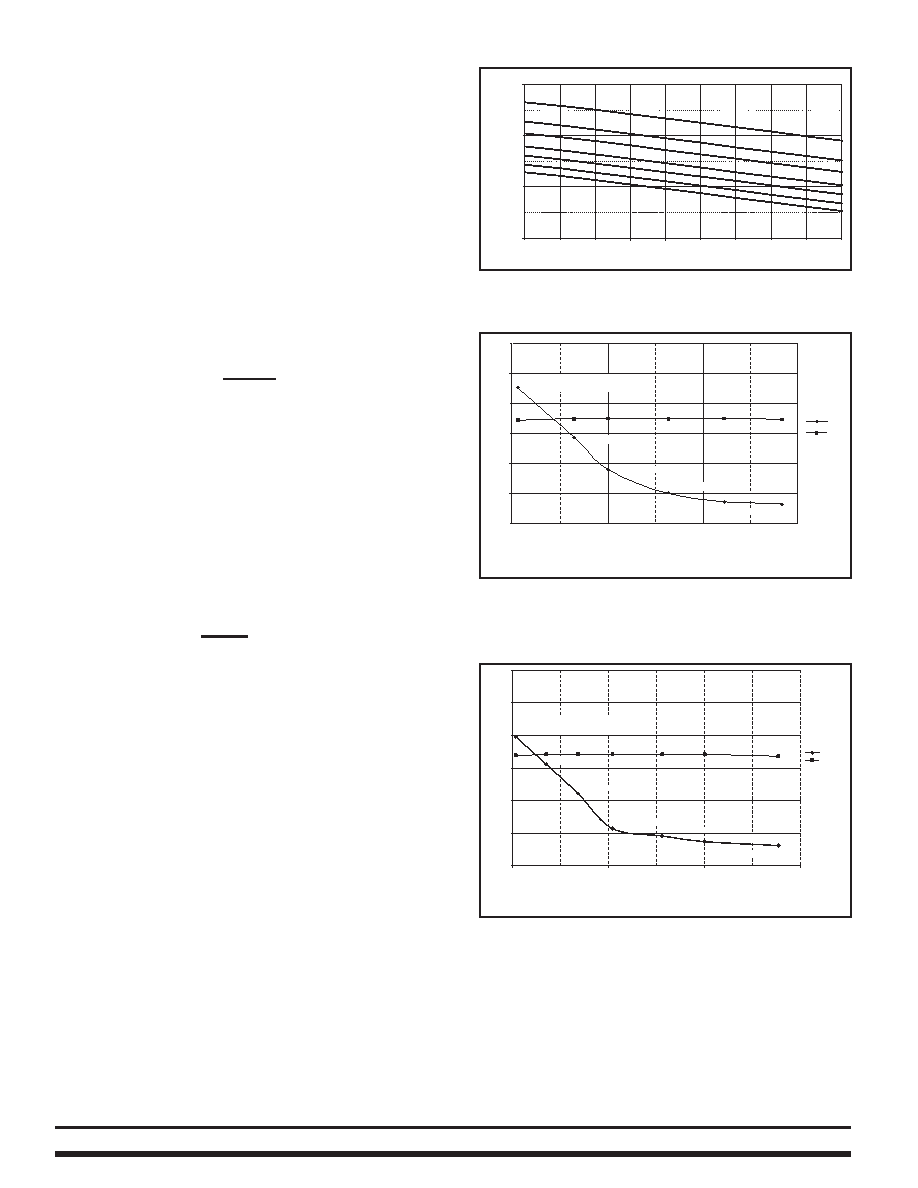
Figures 9 and 10 demonstrate the attenuation versus
power dissipation relationship with different headroom
resistor values with corresponding increasing power
dissipation at a fixed 10 A load. The low frequency
attenuation is flat with changing headroom as indicated
by the 50 Hz line. The active attenuation is dependent on
the headroom voltage and correlates to the attenuation
curves presented previously.
Figure 10 shows the increase in attenuation that can be
gained by using the slope adjust feature setting higher
headroom at lower loads while limiting the power
dissipation with reduced headroom at higher loads staying
within the 4 Watt limitation of the package. As stated
previously this will also increase the transient capability
with a load step providing more delta voltage across the
filter at lower loads.
Iload=10A (Vref Cap=25uF) 1% Rhr std. values for VOUT=3.3V
Rsa=100k (delta Vhr=0mV from 0.1 to 10A)
21 k
24.9 k
30.1 k
39.2 k
47.5 k
-60
-50
-40
-30
-20
-10
0
12
34
Watts
500 khz
50 hz
dB
3.3 V QPO-2 output voltage
69.8 k Headroom resistor
Figure 9 – Power dissipation vs. RHR (Headroom voltage)
113 k
Load Current (A)
1A
2A
3A
4A
5A
6A
7A
8A
9A
10A
0V
200mV
400mV
600mV
V
Headroom
Rhr=64.9 k
75 k
82.5 k
124 k
102 k
93.1 k
Figure 8 – Effect of slope adjust on headroom value with
increasing current and RSA = 8.2 k.
RSA = 0.05(V/A) *
IOUT
* 2.5 k
VHR
RSA = 0.05(V/I) *
5 A
* 2.5 k = 4.167 k
0.15 V
Figure 10 – Power dissipation vs. RHR (Headroom voltage) with
150 mV of slope adjust.
Iload=10A (VREF Cap=25
μF) 1% Rhr std. values for VOUT=3.3V
Rsa=8.4K (delta Vhr=150mV from 0.1 to 10A)
14.3 k
16.5 k
18.2 k
21 k
22.6k
24.9 k
-60
-50
-40
-30
-20
-10
0
1
2
3
4
Watts
dB
500 kHz
50 Hz
3.3 V QPO-2 output voltage
27.4 k Headroom resistor
相關(guān)PDF資料 |
PDF描述 |
|---|---|
| QPO-2LZ | 0.3-5.5V 20A OUT RIP ATTENUATOR |
| RX-4801JE:UB | IC REAL TIME CLOCK MODULE |
| RX-5412SF: B3 PURE SN | IC REAL TIME CLOCK 24-SOP |
| RX-8801SA:UB3 PURE SN | IC REAL TIME CLOCK 14-SOP |
| SA555DX | IC OSC MONO TIMING 8-SOP |
相關(guān)代理商/技術(shù)參數(shù) |
參數(shù)描述 |
|---|---|
| QPP-003 | 制造商:未知廠家 制造商全稱:未知廠家 功能描述:60W, 869-894 MHz Class AB Power Stage |
| QPP-008 | 制造商:未知廠家 制造商全稱:未知廠家 功能描述:35W, 925-960MHz Class AB Driver Stage |
| QPP-015 | 制造商:未知廠家 制造商全稱:未知廠家 功能描述:QuikPAC Module Data |
| QPP-023 | 制造商:未知廠家 制造商全稱:未知廠家 功能描述:QuikPAC Module Data |
| QPP-029 | 制造商:未知廠家 制造商全稱:未知廠家 功能描述:QuikPAC Module Class AB Driver Stage |
發(fā)布緊急采購(gòu),3分鐘左右您將得到回復(fù)。