- 您現(xiàn)在的位置:買賣IC網(wǎng) > PDF目錄361283 > QFBR-5595 5 MBd High Performance Fiber Optic Transmitter and Receiver in Horizontal Pckg PDF資料下載
參數(shù)資料
| 型號: | QFBR-5595 |
| 英文描述: | 5 MBd High Performance Fiber Optic Transmitter and Receiver in Horizontal Pckg |
| 中文描述: | 5 MBd的高性能光纖發(fā)射器和接收器的水平Pckg |
| 文件頁數(shù): | 2/11頁 |
| 文件大小: | 267K |
| 代理商: | QFBR-5595 |

2
Plastic Optical Fiber Specifications: HFBR-R/EXXYYY
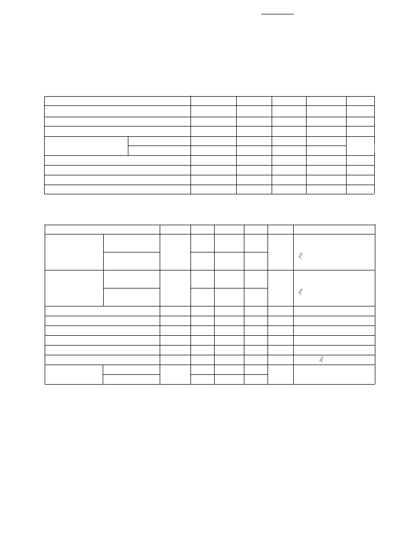
Absolute Maximum Ratings
Parameter
Symbol
T
S,O
T
O
T
I
F
T
F
T
r
r
F
T
Min.
-55
-40
-20
Max.
+85
+85
+70
50
100
Unit
°
C
°
C
°
C
N
N
mm
mm
N
Cycles
Note
Storage and Operating Temperature
Recommended Operating Temperature
Installation Temperature
Short Term Tensile
Force
1
2
Single Channel
Dual Channel
Short Term Bend Radius
Long Term Bend Radius
Long Term Tensile Load
Flexing
25
35
3, 4
1
1000
4
Mechanical/Optical Characteristics, T
A
= -40 to +85
°
C unless otherwise specified.
Parameter
Symbol
Cable
Standard Cable,
α
O
Attenuation
Type "R"
Extra Low Loss,
Type "E"
Reference
Standard Cable,
α
R
Attenuation
Type "R"
Extra Low Loss,
Type "E"
Numerical Aperture
NA
Diameter, Core and Cladding
D
C
Diameter, Jacket
D
J
Propagation Delay Constant
l/v
Mass per Unit Length/Channel
Cable Leakage Current
I
L
Refractive Index
Core
n
Cladding
Min.
0.15
Typ.
[5]
0.22
Max.
0.27
Unit
dB/m
Condition
Source is HFBR-15XX
(660 mm LED, 0.5 NA)
= 50 meters
0.15
0.19
0.23
0.12
0.19
0.24
dB/m
Source is 650 nm,
0.5 NA monochrometer,
= 50 meters
Note 7, Figure 1
>2 meters
0.12
0.16
0.19
0.46
0.94
2.13
0.47
1.00
2.20
5.0
5.3
12
1.492
1.417
0.50
1.06
2.27
mm
mm
ns/m
g/m
nA
Simplex Cable
Note 6
Without Connectors
50 kV,
= 0.3 meters
Notes:
1. Installation temperature is the range over which the cable can be bent and pulled
without damage. Below -20
°
C the cable becomes brittle and should not be subjected to
mechanical stress.
2. Short Term Tensile Force is for less than 30 minutes.
3. Short Term Bend Radius is for less than 1 hour nonoperating.
4. 90
°
bend on 25 mm radius mandrel. Bend radius is the radius of the mandrel around
which the cable is bent.
5. Typical data are at 25
°
C.
6. Propagation delay constant is the reciprocal of the group velocity for propagation delay
of optical power. Group velocity is v=c/n where c is the velocity of light in free space
(3xl0
8
m/s) and n is the effective core index of refraction.
7. Note that
α
R
rises at the rate of about 0.0067 dB/
°
C, where the thermal rise refers to
the LED temperature changes above 25
°
C. Please refer to Figure 1 which shows the
typical plastic optical fiber attenuation versus wavelength at 25
°
C.
相關(guān)PDF資料 |
PDF描述 |
|---|---|
| QFEXR-EVAL-KIT | QFEXR-EVAL-KIT - Evaluation Kit for the Am79C871 Device |
| QFH14 | CONTROL GEAR 14W SINGLE T5 |
| QFH214 | CONTROL GEAR 14W TWIN T5 |
| QFHM1 | CONTROL GEAR 35W SINGLE T5 |
| QFMR5-434 | NOT RoHS. RF inductor, air core, 2% tol, SMT |
相關(guān)代理商/技術(shù)參數(shù) |
參數(shù)描述 |
|---|---|
| QFBR-5595Z | 制造商:AVAGO 制造商全稱:AVAGO TECHNOLOGIES LIMITED 功能描述:Versatile Link The Versatile Fiber Optic Connection |
| QFBR-5651 | 制造商:未知廠家 制造商全稱:未知廠家 功能描述:Gigabit Interface Converters (GBIC) for Gigabit Ethernet |
| QFBR-5689 | 制造商:未知廠家 制造商全稱:未知廠家 功能描述:Multi-mode Gigabit Interface Converter (GBIC) for Gigabit Ethernet |
| QFBR-5690 | 制造商:未知廠家 制造商全稱:未知廠家 功能描述:Gigabit Interface Converters (GBIC) for Gigabit Ethernet |
| QFBR-5896 | 制造商:Rochester Electronics LLC 功能描述: 制造商:Avago Technologies 功能描述: |
發(fā)布緊急采購,3分鐘左右您將得到回復(fù)。