- 您現(xiàn)在的位置:買賣IC網(wǎng) > PDF目錄66051 > PT6606R SWITCHING REGULATOR, SMA14 PDF資料下載
參數(shù)資料
| 型號(hào): | PT6606R |
| 元件分類: | 穩(wěn)壓器 |
| 英文描述: | SWITCHING REGULATOR, SMA14 |
| 封裝: | SIP-14 |
| 文件頁數(shù): | 2/5頁 |
| 文件大小: | 259K |
| 代理商: | PT6606R |
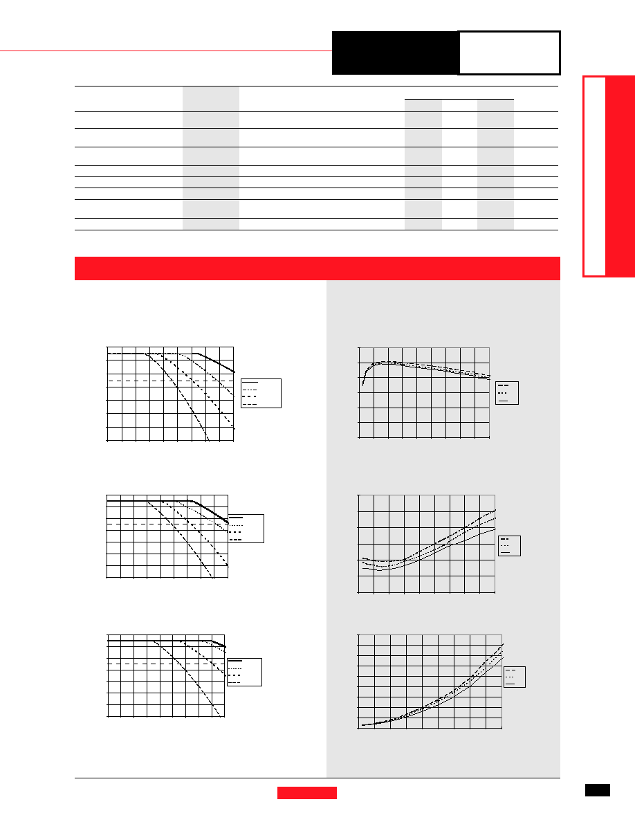
Safe Operating Area Curves (@ Vin=+5.0V) (See Note 2)
PT6601P (Vertical)
Ambient
T
emperature
(°C)
PT6601R (Vertical with Side Tab)
Ambient
T
emperature
(°C)
Ambient
T
emperature
(°C)
Output Current (Amps)
PT6601D (Horizontal)
Airflow
Note 2:
SOA curves represent operating conditions at which internal components are at or below manufacturer’s maximum rated operating temperatures.
Recommended Maximum
Operating Temperature
Recommended Maximum
Operating Temperature
Recommended Maximum
Operating Temperature
CHARACTERISTIC
DA T A
For assistance or to order, call (800) 531-5782
Power Trends, Inc. 27715 Diehl Road, Warrenville, IL 60555 (800) 531-5782 Fax: (630) 393-6902 http://www.powertrends.com
7
3.3V
Bus
Products
DA
T
A
SHEETS
Note 1:
All data listed in the above graphs has been developed from actual products tested at 25°C. This data is considered typical data for the ISR.
PT6601, 3.3 VDC
(See Note 1)
Efficiency vs Output Current
Ripple vs Output Current
Power Dissipation vs Output Current
Efficiency
-
%
Ripple-(mV)
PD-(W
atts)
Iout-(Amps)
PT6600
Series
Specifications (continued)
Characteristics
PT6600 SERIES
(T
a = 25°C unless noted)
Symbols
Conditions
Min
Typ
Max
Units
Switching Frequency
o
3.1V
≤ Vin ≤ 6.0V
475
600
725
kHz
0.1A
≤ Io ≤ 8.0A
Absolute Maximum
Ta
0—
+85
°C
Operating Temperature Range
Recommended Operating
Ta
Free Air Convection (40-60 LFM)
0
—
65**
°C
Temperature Range
Over Vin and Io ranges with heat tab
Thermal Resistance
θ
ja
Free Air Convection (40-60 LFM)
—
25
—
°C/W
Storage Temperature
Ts
—
-40
—
+125
°C
Mechanical Shock
—
Per Mil-STD-883D, Method 2002.3
—
500
—
G’s
Mechanical Vibration
—
Per Mil-STD-883D, Method 2007.2,
—
7.5
—
G’s
20-2000 Hz, soldered in a PC board
Weight
—
14
—
grams
**
See SOA curves
Note:
The PT6600 Series requires two 330F electrolytic capacitors (input and output) for proper operation in all applications.
40
50
60
70
80
90
100
01
234
567
89
4.5V
5.0V
5.5V
Vin
0
5
10
15
20
25
30
012
345
678
9
5.5V
5.0V
4.5V
Vin
0
1
2
3
4
5
6
7
8
9
012
34567
89
5.5V
5.0V
4.5V
Vin
P
20
30
40
50
60
70
80
90
01
234
5678
9
300 LFM
150 LFM
60 LFM
Nat Conv
20
30
40
50
60
70
80
90
012
34
567
89
300 LF M
150 LF M
60 LF M
Na t Co nv.
20
30
40
50
60
70
80
90
012345
6789
300 LF M
150 LF M
60 LF M
Nat Conv
相關(guān)PDF資料 |
PDF描述 |
|---|---|
| PT6606E | SWITCHING REGULATOR, SMA14 |
| PT6604R | SWITCHING REGULATOR, SMA14 |
| PT6606G | SWITCHING REGULATOR, SMA14 |
| PT6602E | SWITCHING REGULATOR, SMA14 |
| PT6605E | SWITCHING REGULATOR, SMA14 |
相關(guān)代理商/技術(shù)參數(shù) |
參數(shù)描述 |
|---|---|
| PT6607 | 制造商:PTC 制造商全稱:Princeton Technology Corp 功能描述:LCD Driver IC |
| PT6607-H | 制造商:PTC 制造商全稱:Princeton Technology Corp 功能描述:LCD Driver IC |
| PT6608 | 制造商:PTC 制造商全稱:Princeton Technology Corp 功能描述:LCD Driver IC |
| PT6608-H | 制造商:PTC 制造商全稱:Princeton Technology Corp 功能描述:LCD Driver IC |
| PT6610 | 制造商:TI 制造商全稱:Texas Instruments 功能描述:9 AMP 5V STEP-DOWN INTEGRATED SWITCHING REGULATOR |
發(fā)布緊急采購,3分鐘左右您將得到回復(fù)。