- 您現(xiàn)在的位置:買賣IC網(wǎng) > PDF目錄66037 > PT4247C (TEXAS INSTRUMENTS INC) 1-OUTPUT 3.9 W DC-DC REG PWR SUPPLY MODULE PDF資料下載
參數(shù)資料
| 型號: | PT4247C |
| 廠商: | TEXAS INSTRUMENTS INC |
| 元件分類: | 電源模塊 |
| 英文描述: | 1-OUTPUT 3.9 W DC-DC REG PWR SUPPLY MODULE |
| 封裝: | SIP-10 |
| 文件頁數(shù): | 5/9頁 |
| 文件大?。?/td> | 191K |
| 代理商: | PT4247C |
Application Notes
For technical support and more information, see inside back cover or visit www.ti.com
Adjusting the Output Voltage of the 10W-Rated
Excalibur Series of Isolated DC/DC Converters
The factory pre-set output voltage of Power Trends’ 10W
Excalibur series of isolated DC-DC converters may be
adjusted over a narrow range. This is accomplished with
the addition of a single external resistor. For the input
voltage range specified in the data sheet, Table 1 gives the
allowable adjustment range for each model as Vo (min)
and Vo (max).
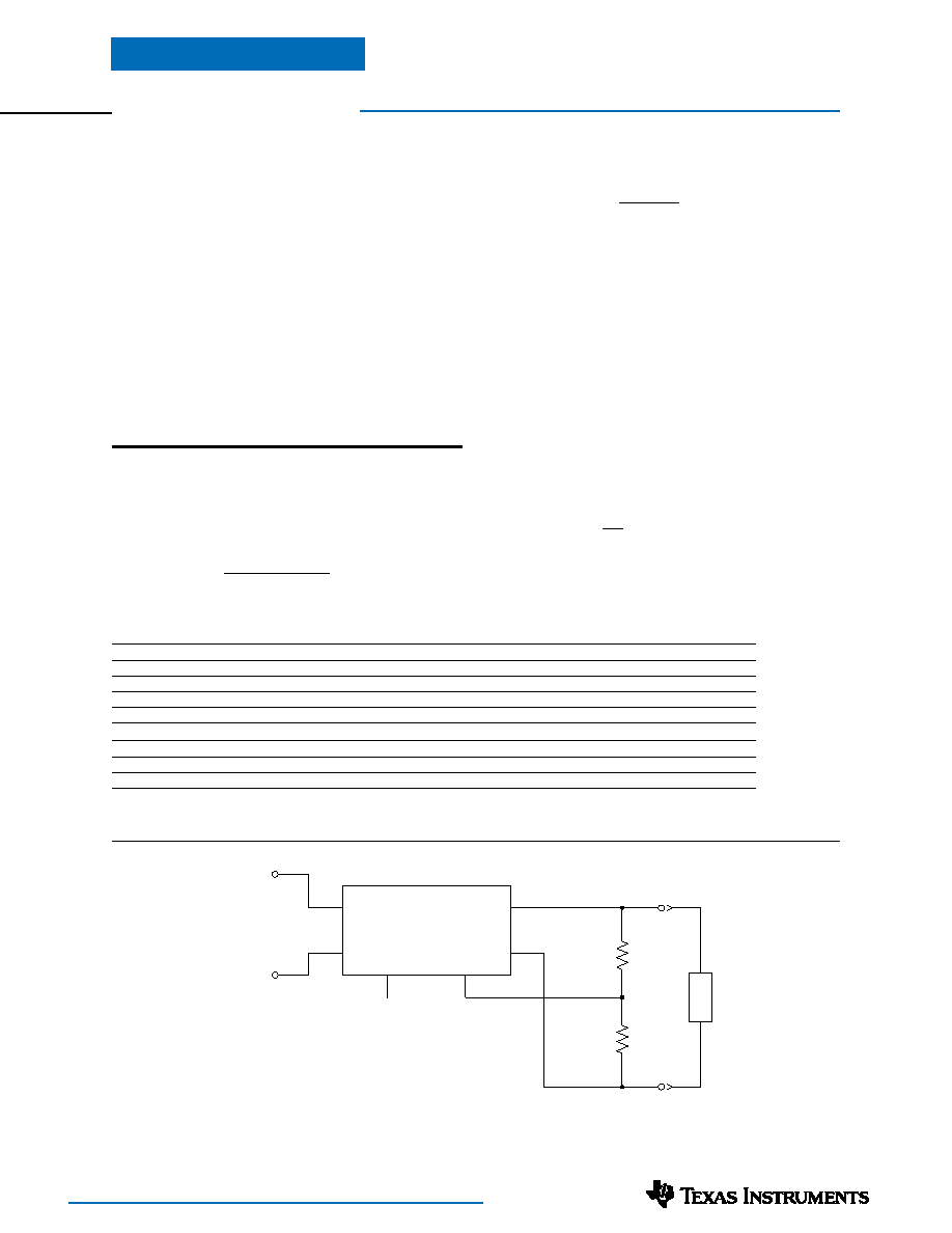
Adjust Up:
An increase in the output voltage is obtained
by adding a resistor, R2 between pin 10 (Vo adjust), and
pins 6 & 7 (–Vout).
Adjust Down:
Add a resistor (R1), between pin 10 (Vo adjust)
and pins 8 & 9 (+Vout).
Refer to Figure 1 and Table 2 for both the placement and value
of the required resistor, (R1) or R2.
The values of (R1) [adjust down], and R2 [adjust up], can
also be calculated using the following formulas.
(R
1)
=
56.2 (V
a – 1.225)
– R
s
k
V
o – Va
Table 1
DC/DC CONVERTER ADJUSTMENT RANGE AND FORMULA PARAMETERS
Series Pt #
24V Bus
PT4247
PT4246
PT4241
PT4245
PT4242
PT4243
PT4244
48V Bus
PT4227
PT4226
PT4221
PT4225
PT4222
PT4223
PT4224
Rated Current 3
3A
2A
0.85A
Vo(nom)
1.3V
1.5V
1.8V
2.5V
3.3V
5.0V
12.0V
Vo(min)
1.2V
1.45V
1.7V
2.25V
2.95V
4.5V
10.8V
Vo(max)
1.4V
1.65V
1.98V
2.75V
3.65V
5.5V
13.2V
Rs (k
)
340.0
243.0
187.0
110.0
49.9
Figure 1
PT4220/4240
+ V out
-V out
+V in
-V in
Remote
On/Off
V
o(adj)
1
3
5
8, 9
6, 7
10
L
O
A
D
+V
in
-V
in
+V
O
–V
O
(R1)
Adj Down
R2
Adjust Up
R
2
=
68.845
– R
s
k
V
a – Vo
Where,
V
o
= Original output voltage
V
a
= Adjusted output voltage
R
s
= Internal resistance (Table 1)
Notes:
1. Use only a single 1% resistor in either the (R1) or R2
location. Place the resistor as close to the ISR as possible.
2. Never connect capacitors to Vo adjust. Any capacitance
added to the Vo adjust control pin will affect the stability of
the ISR.
3. The output power is limited to 10W. If the output
voltage is increased, the maximum load current must be
derated according to the following equation.
I
o(max)
= 10
V
a
In any instance, the load current must not exceed the
converter’s rated current (See Table 1).
PT4220/4240 Series
相關(guān)PDF資料 |
PDF描述 |
|---|---|
| PT4244A | 1-OUTPUT 10 W DC-DC REG PWR SUPPLY MODULE |
| PT4243N | 1-OUTPUT 10 W DC-DC REG PWR SUPPLY MODULE |
| PT4243C | 1-OUTPUT 10 W DC-DC REG PWR SUPPLY MODULE |
| PT4247N | 1-OUTPUT 3.9 W DC-DC REG PWR SUPPLY MODULE |
| PT4245N | 1-OUTPUT 7.5 W DC-DC REG PWR SUPPLY MODULE |
相關(guān)代理商/技術(shù)參數(shù) |
參數(shù)描述 |
|---|---|
| PT4247N | 功能描述:DC/DC轉(zhuǎn)換器 1.3V 3.9W 24V-Input Iso DC/DC Converter RoHS:否 制造商:Murata 產(chǎn)品: 輸出功率: 輸入電壓范圍:3.6 V to 5.5 V 輸入電壓(標(biāo)稱): 輸出端數(shù)量:1 輸出電壓(通道 1):3.3 V 輸出電流(通道 1):600 mA 輸出電壓(通道 2): 輸出電流(通道 2): 安裝風(fēng)格:SMD/SMT 封裝 / 箱體尺寸: |
| PT425 | 制造商:未知廠家 制造商全稱:未知廠家 功能描述:TRIAC|400V V(DRM)|25A I(T)RMS|TO-203AA |
| PT425S | 制造商:未知廠家 制造商全稱:未知廠家 功能描述:TRIAC|400V V(DRM)|25A I(T)RMS|TO-208VAR1/2 |
| PT42CB010 | 制造商:未知廠家 制造商全稱:未知廠家 功能描述:Programmable Delay Line |
| PT42CB020 | 制造商:未知廠家 制造商全稱:未知廠家 功能描述:Programmable Delay Line |
發(fā)布緊急采購,3分鐘左右您將得到回復(fù)。