- 您現(xiàn)在的位置:買賣IC網(wǎng) > PDF目錄65979 > PS20351-N AC MOTOR CONTROLLER, 6 A, DMA35 PDF資料下載
參數(shù)資料
| 型號(hào): | PS20351-N |
| 元件分類: | 運(yùn)動(dòng)控制電子 |
| 英文描述: | AC MOTOR CONTROLLER, 6 A, DMA35 |
| 文件頁數(shù): | 1/9頁 |
| 文件大小: | 149K |
| 代理商: | PS20351-N |
MITSUBISHI SEMICONDUCTOR <Intelligent Power Module>
PS20351-N
TRANSFER-MOLD TYPE
INSULATED TYPE
Sep. 2001
(3.556)
(0.5)
(1.656)
(3.556)
(6.25)
(0.75)
(30.5)
(1.778)
(1.778
× 26)
(6.25) (6.25)
16
17
18
13
14
15
10
987
654
321
11
12
19
20
21
22
23
24
35
34
33
32
31
26 25
27
28
29
30
(8)
(5)
(0.5)
(17.4)
(0.5)
(1.25)
(2.5)
(1.2)
(35°)
A
(6.5)
(10.5)
(1)
PCB
TERMINAL
TERMINAL CODE
1
VUFS
2
(UPG)
3
VUFB
4
VP1
5
(COM)
6
UP
7
VVFS
8
(VPG)
9
VVFB
10
VP1
11
(COM)
12
VP
13
VWFS
14
(WPG)
15
VWFB
16
VP1
17
(COM)
18
WP
19
(UNG)
20
VNO(NC)
21
UN
22
VN
23
WN
24
FO
25
CFO
26
CIN
27
VNC
28
VN1
29
(WNG)
30
(VNG)
31
P
32
U
33
V
34
W
35
N
PATTERN
SLIT
(PCB LAYOUT)
(1)
(1.9)
(0.5)
(1.5)
(1.8MIN)
(0.5)
(1)
HEAT SINK SIDE
Type name , Lot No.
DUMMY PIN
(φ2
DEPTH
2)
(φ3.3)
HEAT SINK SIDE
Detail A
*Note2
(7.62
× 4)
(7.62)
(41)
(42)
(49)
(4MIN)
*Note1:(***) = Dummy Pin.
*Note 2: In order to increase the surface distance between terminals, cut a slit, etc. on the PCB surface
when mounting a module.
PS20351-N
INTEGRATED POWER FUNCTIONS
500V/3A low-loss 4th generation (planar) IGBT inverter
bridge for 3 phase DC-to-AC power conversion.
APPLICATION
AC100V~200V inverter drive for motor control.
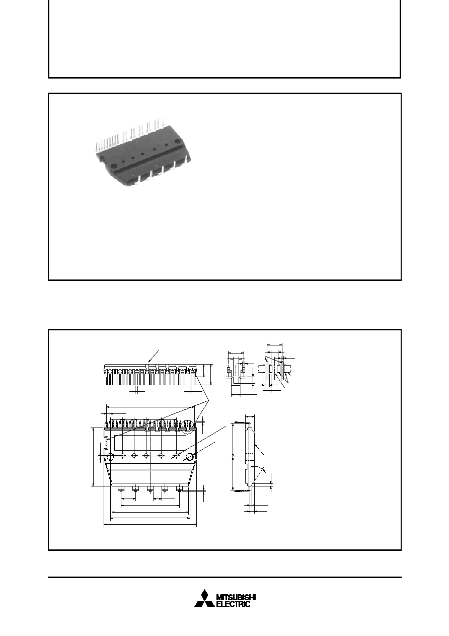
Fig. 1 PACKAGE OUTLINES
MITSUBISHI SEMICONDUCTOR <Intelligent Power Module>
PS20351-N
TRANSFER-MOLD TYPE
INSULATED TYPE
INTEGRATED DRIVE, PROTECTION AND SYSTEM CONTROL FUNCTIONS
For upper-leg IGBTS : Drive circuit, High voltage isolated high-speed level shifting, Control circuit under-voltage (UV) protection.
Note : Bootstrap supply scheme can be applied.
For lower-leg IGBTS : Drive circuit, Control circuit under-voltage protection (UV), Short-circuit protection (SC).
Fault signaling : Corresponding to a SC fault (Low-side IGBT) or a UV fault (Low-side IGBT).
Input interface : 5V line CMOS/TTL compatible, Schmitt Trigger receiver circuit.
Dimensions in mm
相關(guān)PDF資料 |
PDF描述 |
|---|---|
| PS21205 | AC MOTOR CONTROLLER, 20 A, PDIP26 |
| PS21246-EP | AC MOTOR CONTROLLER, 50 A, UFM26 |
| PS21353-G | AC MOTOR CONTROLLER, 20 A, DMA35 |
| PS21353-N | AC MOTOR CONTROLLER, 20 A, DMA35 |
| PS21454-E | AC MOTOR CONTROLLER, 30 A, DMA26 |
相關(guān)代理商/技術(shù)參數(shù) |
參數(shù)描述 |
|---|---|
| PS20351-NP | 制造商:MITSUBISHI 制造商全稱:Mitsubishi Electric Semiconductor 功能描述:Generation DIP and Mini-DIP-IPM |
| PS204 | 制造商:PANJIT 制造商全稱:Pan Jit International Inc. 功能描述:PLASTIC SILICON RECTIFIER |
| PS2041 | 制造商:NEC 制造商全稱:NEC 功能描述:HIGH SPEED 6 PIN PHOTO COUPLER |
| PS2041420 | 制造商:VIKING 功能描述: |
| PS2043 | 制造商:NEC 制造商全稱:NEC 功能描述:PHOTO COUPLER |
發(fā)布緊急采購,3分鐘左右您將得到回復(fù)。