- 您現(xiàn)在的位置:買賣IC網(wǎng) > PDF目錄98060 > PQ60280FTA26NYS-G (SYNQOR INC) 1-OUTPUT DC-DC REG PWR SUPPLY MODULE PDF資料下載
參數(shù)資料
| 型號: | PQ60280FTA26NYS-G |
| 廠商: | SYNQOR INC |
| 元件分類: | 電源模塊 |
| 英文描述: | 1-OUTPUT DC-DC REG PWR SUPPLY MODULE |
| 封裝: | ROHS COMPLIANT, FULL BRICK PACKAGE-18 |
| 文件頁數(shù): | 9/14頁 |
| 文件大?。?/td> | 658K |
| 代理商: | PQ60280FTA26NYS-G |
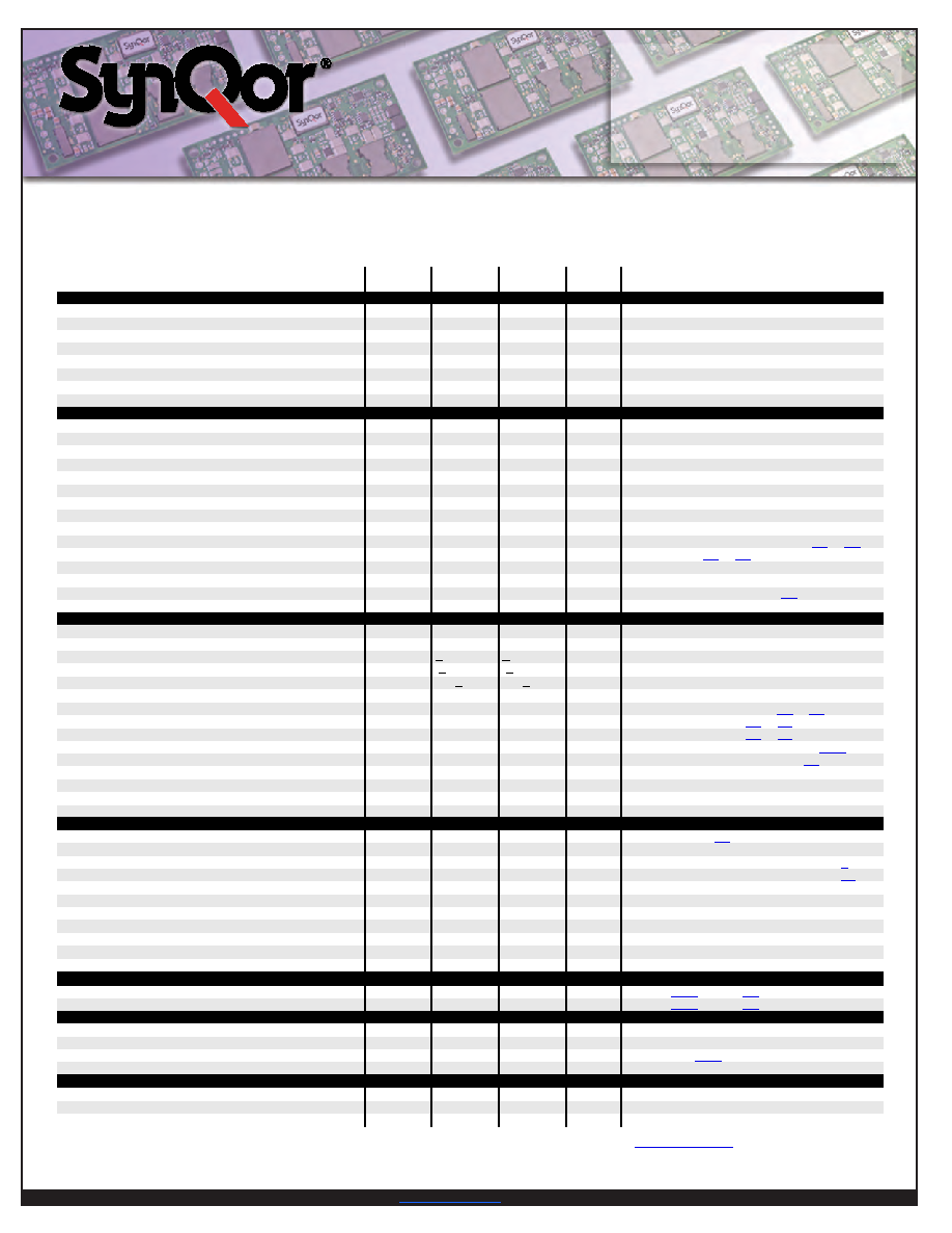
Product # PQ60280FTA26
Phone 1-888-567-9596
Doc.# 005-2FT628P Rev. C
5/21/08
Page 4
T
Technical S
echnical Specification
pecification
Input:
Output:
Current:
PPackage:
ackage:
36-75 V
28 V
26 A
Full-brick
Parameter
Min.
Typ.
Max.
Units
Notes & Conditions
ABSOLUTE MAXIMUM RATINGS
Input Voltage
Non-Operating
100
V
Continuous
Operating
80
V
Continuous
Operating Transient Protection
100
V
100ms transient
Isolation Voltage (input to output)
2250
V
Basic insulation level, Pollution degree 2
Operating Temperature
-40
100
°C
Storage Temperature
-55
125
°C
Voltage at ON/OFF input pin
-2
18
V
INPUT CHARACTERISTICS
Operating Input Voltage Range
36
48
75
V
Input Under-Voltage Lockout
Turn-On Voltage Threshold
31.5
33.3
34.7
V
Turn-Off Voltage Threshold
29.5
31.0
32.4
V
Lockout Voltage Hysteresis
2.3
V
Maximum Input Current
22.0
A
100% Load, 36 Vin
No-Load Input Current
220
250
mA
Disabled Input Current
42
65
mA
Inrush Current Transient Rating
0.1
A2s
Input Reflected Ripple Current
60
mA
Input Terminal Ripple Current
3
A
Recommended Input Fuse
30
A
Fast blow external fuse recommended
Input Filter Component Values (L\C)
0.2 \ 8.0
H\F
Internal values
Recommended External Input Capacitance
200
F
Typical ESR 0.2W, see Figure
Recommended External Input Capacitor ESR1
0.04
0.20
1.00
W
100kHz, -40C to 100C
OUTPUT CHARACTERISTICS
Output Voltage Set Point
27.75
28.00
28.25
V
Output Voltage Regulation
Over Line
+0.05 \ 28 +0.10 \ 28 %\mV
Over Load
+0.1 \ 28 +0.2 \ 56
%\mV
Over Temperature
+45
+90
mV
Total Output Voltage Range
27.50
28.50
V
Over sample, line, load, temperature & life
Output Voltage Ripple and Noise1
Peak-to-Peak
180
250
mV
RMS
40
50
mV
Operating Output Current Range
0
26
A
Subject to thermal derating; Figures 5 - 6
Output DC Current-Limit Inception
28.0
30.2
32.0
A
Output Voltage 10% Low; Figure 22
Back-Drive Current-Limit While Enabled
1.50
3.40
5.00
A
Negative current drawn from output
Back-Drive Current-Limit While Disabled
0.14
0.30
0.45
A
Negative current drawn from output
Current Share Accuracy (2 units paralleled)
2.5
A
Maximum Output Capacitance
4,000
F
28Vout at 26A Resistive Load
DYNAMIC CHARACTERISTICS
Input Voltage Ripple Rejection
30
dB
120 Hz; Figure 18
Output Voltage during Load Current Transient
For a Step Change in Output Current (0.1A/s)
1500
mV
50-75-50% Iout max; 47F cap; Figure 9
For a Step Change in Output Current (5A/s)
800
mV
50-75-50% Iout max; 47F cap; Figure 10
Settling Time
150
s
To within 1% Vout nom
Turn-On Transient
Turn-On Time
25
30
35
ms
Startup Delay:
2
ms
First Startup Delay:
200
ms
Restart Inhibit Delay:
320
ms
Output Voltage Overshoot
0
%
4,000 F load capacitance, Iout = 26A resistive load
EFFICIENCY
100% Load
95
%
50% Load
96
%
TEMPERATURE LIMITS FOR POWER DERATING CURVES
Semiconductor Junction Temperature
125
°C
Package rated to 150°C
Board Temperature
125
°C
UL rated max operating temp 130°C
Transformer Temperature
125
°C
See Figures 5 - 6 for derating curve
Maximum Baseplate Temperature2
100
°C
Applies to baseplated units only
ISOLATION CHARACTERISTICS
Isolation Voltage (dielectric strength)
2250
V
Isolation Resistance
30
MW
Isolation Capacitance3
3300
pF
PQ60280FTA26 ELECTRICAL CHARACTERISTICS
TA=25°C, airflow rate=300 LFM, Vin=48Vdc unless otherwise noted; full operating temperature range is -40°C to +100°C ambient
temperature with appropriate power derating. Specifications subject to change without notice.
Note 1: For applications requiring reduced output voltage ripple and noise, consult SynQor applications support (e-mail: support@synqor.com)
Note 2: There is no derating with a baseplate temperature of 100C or lower.
Note 3: Higher values of isolation capacitance can be added external to the module.
相關PDF資料 |
PDF描述 |
|---|---|
| PQ60480QTA03NRS-G | 1-OUTPUT 144 W DC-DC REG PWR SUPPLY MODULE |
| PQ60480QTA03PYS-G | 1-OUTPUT 144 W DC-DC REG PWR SUPPLY MODULE |
| PQ60480QTA03PKS-G | 1-OUTPUT 144 W DC-DC REG PWR SUPPLY MODULE |
| PQ60480QTA03PNS-G | 1-OUTPUT 144 W DC-DC REG PWR SUPPLY MODULE |
| PQ60480QTA03NYS-G | 1-OUTPUT 144 W DC-DC REG PWR SUPPLY MODULE |
相關代理商/技術參數(shù) |
參數(shù)描述 |
|---|---|
| PQ60280FTA26PKF-G | 制造商:SYNQOR 制造商全稱:SYNQOR 功能描述:Full-brick DC/DC Converter |
| PQ60280FTA26PKS-G | 制造商:SYNQOR 制造商全稱:SYNQOR 功能描述:Full-brick DC/DC Converter |
| PQ60280FTA26PNF-G | 制造商:SYNQOR 制造商全稱:SYNQOR 功能描述:Full-brick DC/DC Converter |
| PQ60280FTA26PNS-G | 制造商:SYNQOR 制造商全稱:SYNQOR 功能描述:Full-brick DC/DC Converter |
| PQ60280FTA26PRF-G | 制造商:SYNQOR 制造商全稱:SYNQOR 功能描述:Full-brick DC/DC Converter |
發(fā)布緊急采購,3分鐘左右您將得到回復。