- 您現(xiàn)在的位置:買賣IC網(wǎng) > PDF目錄65966 > PM75RVA060 AC MOTOR CONTROLLER, 150 A, XMA25 PDF資料下載
參數(shù)資料
| 型號: | PM75RVA060 |
| 元件分類: | 運動控制電子 |
| 英文描述: | AC MOTOR CONTROLLER, 150 A, XMA25 |
| 文件頁數(shù): | 4/7頁 |
| 文件大小: | 117K |
| 代理商: | PM75RVA060 |
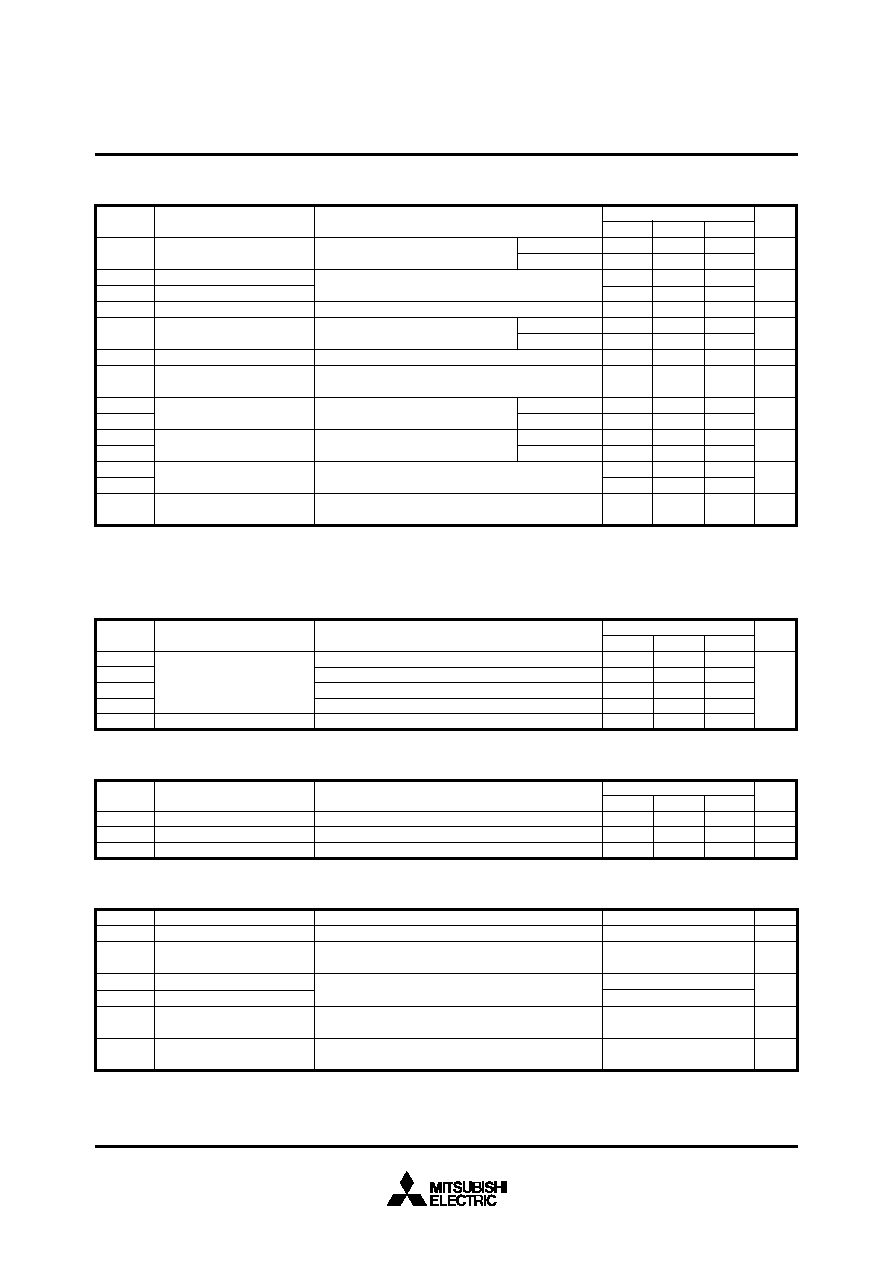
MITSUBISHI <INTELLIGENT POWER MODULES>
PM75RVA060
FLAT-BASE TYPE
INSULATED PACKAGE
Jun. 2005
3.5
—
Mounting part
screw : M5
Main terminal
screw : M5
—
Symbol
Parameter
Mounting torque
Weight
Test Condition
Unit
N m
g
Limits
Min.
Typ.
Max.
2.5
—
3.0
560
MECHANICAL RATINGS AND CHARACTERISTICS
(Note-2) Fault output is given only when the internal SC, OT & UV protection.
Fault output of OT protection operate by lower arm.
Fault output of OT, UV protection given pulse while over level.
VD = 15V
Base-plate
Temperature detection, VD = 15V
–20
≤ Tj ≤ 125°C
VD = 15V, VFO = 15V
(Note-2)
VD = 15V
(Note-2)
Trip level
Reset level
Trip level
Reset level
Circuit Current
Input ON Threshold Voltage
Input OFF Threshold Voltage
Over Current Trip Level
Short Circuit Trip Level
Over Current Delay Time
Short Circuit Current Delay
Time
Over Temperature Protection
Supply Circuit Under-Voltage
Protection
Fault Output Current
Minimum Fault Output Pulse
Width
Vth(ON)
Vth(OFF)
OC
SC
toff(OC)
toff(SC)
OT
OTr
UV
UVr
IFO(H)
IFO(L)
tFO
–20
≤ Tj ≤ 125°C, VD = 15V, Break part
–20
≤ Tj ≤ 125°C, VD = 15V
VD = 15V, Break part
Inverter part
Brake part
CONTROL PART
ID
Parameter
Symbol
s
°C
V
mA
ms
60
18
1.8
2.3
—
125
—
12.5
—
0.01
15
—
mA
—
1.2
1.7
39
115
—
111
—
11.5
—
1.0
Max.
Min.
Typ.
Unit
Limits
44
13
1.5
2.0
—
94
10
118
100
12.0
12.5
—
10
1.8
V
s
A
VD = 15V, VCIN = 15V
Applied between : UP-VUPC, VP-VVPC, WP-VWPC
UN VN WN Br-VNC
Test Condition
VN1-VNC
V*P1-V*PC
Rth(j-c)Q
Rth(j-c)F
Rth(j-c)Q
Rth(j-c)F
Rth(c-f)
Symbol
THERMAL RESISTANCES
0.44
0.96
0.70
1.50
0.027
°C/W
Inverter IGBT part (per 1/6 module)
Inverter FWDi part (per 1/6 module)
Brake IGBT part
Brake FWDi part
Case to fin, Thermal grease applied (per 1 module)
Parameter
Test Condition
Unit
Limits
Min.
Typ.
Max.
—
Junction to case Thermal
Resistances
Contact Thermal Resistance
RECOMMENDED CONDITIONS FOR USE
Recommended value
Unit
Test Condition
Symbol
Parameter
V
Applied across P-N terminals
Applied between : VUP1-VUPC, VVP1-VVPC
VWP1-VWPC, VN1-VNC
(Note-3)
Applied between : UP-VUPC, VP-VVPC, WP-VWPC
UN VN WN Br-VNC
For IPM’s each input signals
Using Application Circuit input signal of IPM,
Sinusoidal PWM VVVF inverter
Supply Voltage
Control Supply Voltage
Input ON Voltage
Input OFF Voltage
Arm Shoot-through
Blocking Time
PWM Input Frequency
≤ 400
15
± 1.5
≤ 0.8
≥ 4.0
≥ 2.5
≤ 20
VCC
VCIN(ON)
VCIN(OFF)
tdead
fPWM
VD
V
s
kHz
V
(Note-3) With ripple satisfying the following conditions dv/dt swing
≤ ±5V/s, Variation ≤ 2V peak to peak
相關(guān)PDF資料 |
PDF描述 |
|---|---|
| PM772 | 2-OUTPUT 3 W DC-DC REG PWR SUPPLY MODULE |
| PM752 | 2-OUTPUT 3 W DC-DC REG PWR SUPPLY MODULE |
| PM721 | 1-OUTPUT 3 W DC-DC REG PWR SUPPLY MODULE |
| PM711 | 1-OUTPUT 3 W DC-DC REG PWR SUPPLY MODULE |
| PM861 | 2-OUTPUT DC-DC REG PWR SUPPLY MODULE |
相關(guān)代理商/技術(shù)參數(shù) |
參數(shù)描述 |
|---|---|
| PM75RVA060_05 | 制造商:MITSUBISHI 制造商全稱:Mitsubishi Electric Semiconductor 功能描述:FLAT-BASE TYPE INSULATED PACKAGE |
| PM75RVA060_11 | 制造商:MITSUBISHI 制造商全稱:Mitsubishi Electric Semiconductor 功能描述:FLAT-BASE TYPE INSULATED PACKAGE |
| PM75-XXXK | 制造商:未知廠家 制造商全稱:未知廠家 功能描述:SMT POWER INDUCTORS |
| PM761 | 制造商:未知廠家 制造商全稱:未知廠家 功能描述:Analog IC |
| PM762 | 制造商:ARTESYN 制造商全稱:Artesyn Technologies 功能描述:Single and dual output 3 Watt Nominal input DC/DC converters |
發(fā)布緊急采購,3分鐘左右您將得到回復(fù)。