- 您現(xiàn)在的位置:買賣IC網(wǎng) > PDF目錄65942 > PKF4110BSI (ERICSSON POWER MODULES AB) 1-OUTPUT 13.2 W DC-DC REG PWR SUPPLY MODULE PDF資料下載
參數(shù)資料
| 型號(hào): | PKF4110BSI |
| 廠商: | ERICSSON POWER MODULES AB |
| 元件分類: | 電源模塊 |
| 英文描述: | 1-OUTPUT 13.2 W DC-DC REG PWR SUPPLY MODULE |
| 封裝: | PLASTIC, SMD-18 |
| 文件頁數(shù): | 4/8頁 |
| 文件大小: | 491K |
| 代理商: | PKF4110BSI |
4
EN/LZT 146 57 R1A Ericsson Microelectronics AB, March 2001
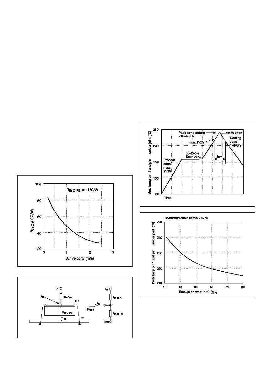
Thermal Data
Two-parameter model
This model provides a more precise description of the thermal char-
acteristics to be used for thermal calculations.
Thermally the power module can be considered as a component and
the case temperature can be used to characterize the properties. The
thermal data for a power module with the substrate in contact with
the case can be described with two thermal resistances. One from
case to ambient air and one from case to PB (Printed circuit Board).
The thermal characteristics temperature can be calculated from the
following formula:
Palladium plating is used on the terminal pins. A pin temperature (Tp)
in excess of the solder fusing temperature (+183°C for Sn/Pb 63/37)
for more than 25 seconds and a peak temperature above 195°C, is
required to guarantee a reliable solder joint.
Both pin 1 and pin 11 must be monitored.
No responsibility is assumed if these recommendations are not
strictly followed.
Reflow Soldering Information
The PKF series of DC/DC power modules are manufactured in sur-
face mount technology. Extra precautions must therefore be taken
when reflow soldering the surface mount version. Neglecting the
soldering information given below may result in permanent damage
or significant degradation of power module performance.
The PKF series can be reflow soldered using IR, Natural Convection,
Forced Convection or Combined IR/Convection Technologies. The
high thermal mass of the component and its effect on
DT (°C) re-
quires that particular attention be paid to other temperature sensi-
tive components.
IR Reflow technology may require the overall profile time to be
extended to approximately 8–10 minutes to ensure an acceptable
DT. Higher activity flux may be more suitable to overcome the
increase in oxidation and to avoid flux burn-up.
The general profile parameters detailed in the diagram, with this ex-
tended time to reach peak temperatures, would then be suitable.
Note! These are maximum parameters. Depending on process varia-
tions, an appropriate margin must be added.
TPB = (TC–TA)×(Rth C–PB+Rth C–A)/Rth C–A–Pd×Rth C–PB+TA
Where:
Pd:
dissipated power, calculated as PO ×(l/h–1)
TC:
max average case temperature
TA:
ambient air temperature at the lower side of the
power module
TPB:
temperature in the PB between the PKF connection pins
Rth C-PB: thermal resistance from case to PB under the
power module
Rth C-A: thermal resistance from case to ambient air
v:
velocity of ambient air
Rth C-PB is constant and Rth C-A is dependent on the air velocity.
Free convection is equal to an air velocity of aprox. 0.2 – 0.3 m/s.
See figure below.
Figure 4
11
相關(guān)PDF資料 |
PDF描述 |
|---|---|
| PKF4611SI | 1-OUTPUT 6 W DC-DC REG PWR SUPPLY MODULE |
| PKF5617PI | 1-OUTPUT 6 W DC-DC REG PWR SUPPLY MODULE |
| PKF5510PI | 1-OUTPUT 5 W DC-DC REG PWR SUPPLY MODULE |
| PKF2611SI | 1-OUTPUT 6 W DC-DC REG PWR SUPPLY MODULE |
| PKF4622PI | 2-OUTPUT 6 W DC-DC REG PWR SUPPLY MODULE |
相關(guān)代理商/技術(shù)參數(shù) |
參數(shù)描述 |
|---|---|
| PKF4111ASI | 制造商:Ericsson 功能描述:MODULE EOL310305 |
| PKF4111A-SI | 制造商:Ericsson 功能描述:DC to DC Converter, +5.05V, 18 Pin, DIP |
| PKF4310 | 制造商:ERICSSON 制造商全稱:Ericsson 功能描述:3?7 W DC/DC Power Modules 48 V Input Series |
| PKF4310PI | 制造商:Ericsson 功能描述: |
| PKF4310SI | 制造商:ERICSSON 制造商全稱:Ericsson 功能描述:3?7 W DC/DC Power Modules 48 V Input Series |
發(fā)布緊急采購,3分鐘左右您將得到回復(fù)。