- 您現(xiàn)在的位置:買賣IC網(wǎng) > PDF目錄299771 > PIC12F635T-E/SN 8-BIT, FLASH, 20 MHz, RISC MICROCONTROLLER, PDSO8 PDF資料下載
參數(shù)資料
| 型號: | PIC12F635T-E/SN |
| 元件分類: | 微控制器/微處理器 |
| 英文描述: | 8-BIT, FLASH, 20 MHz, RISC MICROCONTROLLER, PDSO8 |
| 封裝: | 0.150 INCH, PLASTIC, MS-012, SOIC-8 |
| 文件頁數(shù): | 124/196頁 |
| 文件大?。?/td> | 3291K |
| 代理商: | PIC12F635T-E/SN |
第1頁第2頁第3頁第4頁第5頁第6頁第7頁第8頁第9頁第10頁第11頁第12頁第13頁第14頁第15頁第16頁第17頁第18頁第19頁第20頁第21頁第22頁第23頁第24頁第25頁第26頁第27頁第28頁第29頁第30頁第31頁第32頁第33頁第34頁第35頁第36頁第37頁第38頁第39頁第40頁第41頁第42頁第43頁第44頁第45頁第46頁第47頁第48頁第49頁第50頁第51頁第52頁第53頁第54頁第55頁第56頁第57頁第58頁第59頁第60頁第61頁第62頁第63頁第64頁第65頁第66頁第67頁第68頁第69頁第70頁第71頁第72頁第73頁第74頁第75頁第76頁第77頁第78頁第79頁第80頁第81頁第82頁第83頁第84頁第85頁第86頁第87頁第88頁第89頁第90頁第91頁第92頁第93頁第94頁第95頁第96頁第97頁第98頁第99頁第100頁第101頁第102頁第103頁第104頁第105頁第106頁第107頁第108頁第109頁第110頁第111頁第112頁第113頁第114頁第115頁第116頁第117頁第118頁第119頁第120頁第121頁第122頁第123頁當前第124頁第125頁第126頁第127頁第128頁第129頁第130頁第131頁第132頁第133頁第134頁第135頁第136頁第137頁第138頁第139頁第140頁第141頁第142頁第143頁第144頁第145頁第146頁第147頁第148頁第149頁第150頁第151頁第152頁第153頁第154頁第155頁第156頁第157頁第158頁第159頁第160頁第161頁第162頁第163頁第164頁第165頁第166頁第167頁第168頁第169頁第170頁第171頁第172頁第173頁第174頁第175頁第176頁第177頁第178頁第179頁第180頁第181頁第182頁第183頁第184頁第185頁第186頁第187頁第188頁第189頁第190頁第191頁第192頁第193頁第194頁第195頁第196頁
2005 Microchip Technology Inc.
Preliminary
DS41232B-page 31
PIC12F635/PIC16F636/639
3.3.2
EC MODE
The External Clock (EC) mode allows an externally
generated logic level as the system clock source.
When operating in this mode, an external clock source
is connected to the OSC1 pin and the RA5 pin is
available for general purpose I/O. Figure 3-2 shows the
pin connections for EC mode.
The Oscillator Start-up Timer (OST) is disabled when
EC mode is selected. Therefore, there is no delay in
operation after a Power-on Reset (POR) or wake-up
from Sleep. Because the PIC12F635/PIC16F636/639
design is fully static, stopping the external clock input
will have the effect of halting the device while leaving all
data intact. Upon restarting the external clock, the
device will resume operation as if no time had elapsed.
FIGURE 3-2:
EXTERNAL CLOCK (EC)
MODE OPERATION
3.3.3
LP, XT, HS MODES
The LP, XT and HS modes support the use of quartz
crystal resonators or ceramic resonators connected to
the OSC1 and OSC2 pins (Figure 3-1). The mode
selects a low, medium or high gain setting of the
internal inverter-amplifier to support various resonator
types and speed.
LP Oscillator mode selects the lowest gain setting of
the
internal
inverter-amplifier.
LP
mode
current
consumption is the least of the three modes. This mode
is best suited to drive resonators with a low drive level
specification, for example, tuning fork type crystals.
XT Oscillator mode selects the intermediate gain
setting of the internal inverter-amplifier. XT mode
current consumption is the medium of the three modes.
This mode is better suited to drive resonators with a
medium drive level specification, for example, low-
frequency AT-cut quartz crystal resonators.
HS Oscillator mode selects the highest gain setting of
the
internal
inverter-amplifier.
HS
mode
current
consumption is the highest of the three modes. This
mode is better suited for resonators that require a high
drive setting, for example, high-frequency AT-cut
quartz crystal resonators or ceramic resonators.
Figure 3-3 and Figure 3-4 show typical circuits for
quartz crystal and ceramic resonators, respectively.
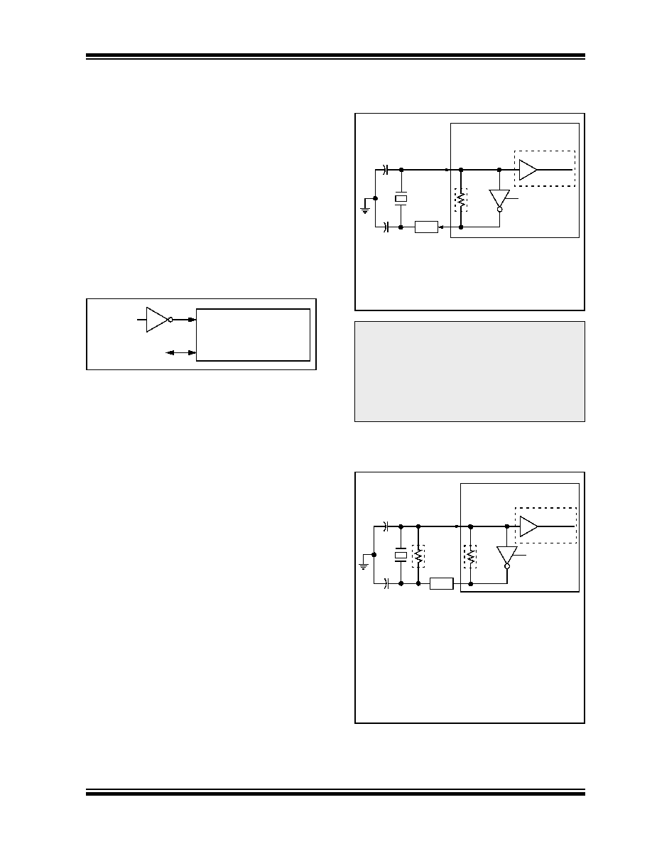
FIGURE 3-3:
QUARTZ CRYSTAL
OPERATION (LP, XT OR
HS MODE)
FIGURE 3-4:
CERAMIC RESONATOR
OPERATION
(XT OR HS MODE)
OSC1/CLKIN
I/O (OSC2)
RA4
Clock from
Ext. System
PIC12F635/PIC16F636/639
Note 1: Quartz
crystal
characteristics
vary
according
to
type,
package
and
manufacturer. The user should consult the
manufacturer data sheets for specifications
and recommended application.
2: Always verify oscillator performance over
the VDD and temperature range that is
expected for the application.
Note 1:
A series resistor (RS) may be required for
quartz crystals with low drive level.
2:
The value of RF varies with the Oscillator
mode selected (typically between 2 M
Ω to
10 M
Ω).
C1
C2
Quartz
OSC2
RS(1)
OSC1
RF(2)
Sleep
PIC12F635/PIC16F636/639
Crystal
To Internal
Logic
Note
1: A series resistor (RS) may be required for
ceramic resonators with low drive level.
2: The value of RF varies with the Oscillator
mode selected (typically between 2 M
Ω to
10 M
Ω).
3: An additional parallel feedback resistor (RP)
may be required for proper ceramic resonator
operation (typical value 1 M
Ω).
C1
C2 Ceramic
OSC2
RS(1)
OSC1
RP(3)
Resonator
RF(2)
Sleep
PIC12F635/PIC16F636/639
To Internal
Logic
相關(guān)PDF資料 |
PDF描述 |
|---|---|
| PIC16C65B-04I/PQ | 8-BIT, OTPROM, 4 MHz, RISC MICROCONTROLLER, PQFP44 |
| PIC16C73BT-20E/SS | 8-BIT, OTPROM, 20 MHz, RISC MICROCONTROLLER, PDSO28 |
| PIC16C74B-04I/P | 8-BIT, OTPROM, 4 MHz, RISC MICROCONTROLLER, PDIP40 |
| PIC16LC73B-04I/SS | 8-BIT, OTPROM, 4 MHz, RISC MICROCONTROLLER, PDSO28 |
| PIC16LC74B-04I/P | 8-BIT, OTPROM, 4 MHz, RISC MICROCONTROLLER, PDIP40 |
相關(guān)代理商/技術(shù)參數(shù) |
參數(shù)描述 |
|---|---|
| PIC12F635T-I/MD | 功能描述:8位微控制器 -MCU 2 KB 64 RAM 6I/O RoHS:否 制造商:Silicon Labs 核心:8051 處理器系列:C8051F39x 數(shù)據(jù)總線寬度:8 bit 最大時鐘頻率:50 MHz 程序存儲器大小:16 KB 數(shù)據(jù) RAM 大小:1 KB 片上 ADC:Yes 工作電源電壓:1.8 V to 3.6 V 工作溫度范圍:- 40 C to + 105 C 封裝 / 箱體:QFN-20 安裝風(fēng)格:SMD/SMT |
| PIC12F635TI/MF | 制造商:MICROCHIP 制造商全稱:Microchip Technology 功能描述:8/14-PIN FLASH-BASED, 8-BIT CMOS MICROCONTROLLERS WITH NANOWATT TECHNOLOGY |
| PIC12F635T-I/MF | 功能描述:8位微控制器 -MCU 2kb 64 RAM 6 I/O RoHS:否 制造商:Silicon Labs 核心:8051 處理器系列:C8051F39x 數(shù)據(jù)總線寬度:8 bit 最大時鐘頻率:50 MHz 程序存儲器大小:16 KB 數(shù)據(jù) RAM 大小:1 KB 片上 ADC:Yes 工作電源電壓:1.8 V to 3.6 V 工作溫度范圍:- 40 C to + 105 C 封裝 / 箱體:QFN-20 安裝風(fēng)格:SMD/SMT |
| PIC12F635TI/MFQTP | 制造商:MICROCHIP 制造商全稱:Microchip Technology 功能描述:8/14-PIN FLASH-BASED, 8-BIT CMOS MICROCONTROLLERS WITH NANOWATT TECHNOLOGY |
| PIC12F635TI/P | 制造商:MICROCHIP 制造商全稱:Microchip Technology 功能描述:8/14-PIN FLASH-BASED, 8-BIT CMOS MICROCONTROLLERS WITH NANOWATT TECHNOLOGY |
發(fā)布緊急采購,3分鐘左右您將得到回復(fù)。