- 您現(xiàn)在的位置:買賣IC網(wǎng) > PDF目錄383740 > PDC-20A-5 (MINI-CIRCUITS) 6 to 30 dB COUPLING up to 10W 5 kHz to 2000 MHz PDF資料下載
參數(shù)資料
| 型號(hào): | PDC-20A-5 |
| 廠商: | MINI-CIRCUITS |
| 元件分類: | 衰減器 |
| 英文描述: | 6 to 30 dB COUPLING up to 10W 5 kHz to 2000 MHz |
| 中文描述: | 0.1 MHz - 2000 MHz RF/MICROWAVE DIRECTIONAL COUPLER, 2.9 dB INSERTION LOSS-MAX |
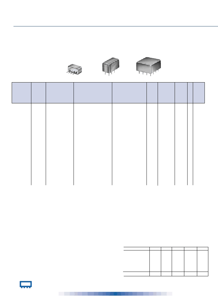
| 封裝: | HERMETIC SEALED, CASE C145, 16 PIN |
| 文件頁(yè)數(shù): | 1/1頁(yè) |
| 文件大小: | 46K |
| 代理商: | PDC-20A-5 |
INTERNET
http://www.minicircuits.com
P.O. Box 350166, Brooklyn, New York 11235-0003 (718) 934-4500 Fax (718) 332-4661
Distribution Centers
NORTH AMERICA 800-654-7949 417-335-5935 Fax 417-335-5945 E
UROPE 44-1252-832600
Fax 44-1252-837010
ISO 9001 CERTIFIED
Mini-Circuits
0
NOTES:
*
L = 25-50 MHz, M = 50-300 MHz, U = 300-400 MHz
**
Upper range coupling ±0.75 dB
L = 40-100 MHz, M = 100-200 MHz
L = f
-2f
4-coupled ports, Isolation between coupled ports, 25 dB minimum.
Insertion loss specification in L range may degrade up to 1dB at
cold temperature, -55°C
When only specification for M or MU range given, specification
applies to entire frequency range.
Denotes 75 Ohm models
A.
General Quality C ontrol Procedures, Environmental
Specifications, Hi-Rel and MIL description are given in General
Information (Section 0).
B.
C onnector types and case mounted options, case finishes are
given in section 0, see “C ase styles & Outline Drawings".
C.
Prices and specifications subject to change without notice.
1.
Mainline Loss includes theoretical power loss at coupled port.
2.
For PDC -HP models, external heat sinking is recommended to
reduce case temperature.
TDC -6-1
TDC -10-1
TDC -10-2
10-400
1-400
5-1000
6.3±0.4
10.0±0.5
11.0±0.5
±0.4
±0.5
±0.6
2.0
1.2
1.4
2.4
1.5
1.8
2.0
1.0
1.5
2.4
1.3
1.8
2.0
1.2
1.6
2.5
1.5
2.0
36
35
50
30
25
35
30 25
30 20
25 20
20 15
20 15
20 15
1.5
1.5
1.5
1.0
1.0
0.5
2.0
2.0
0.5
B02
B02
B02
c w
c w
c w
23.95
17.95
25.95
PDC -10-1
PDC -10-2
PDC -10-5
PDC -10-6
0.5-500
250-1000
1-2000
0.005-20
11.5±0.5
10.5±0.5
10.5±0.5
11.0±0.5
±0.6
±0.6
±1.0
±0.5
0.85 1.3
1.4
1.2
0.4
0.65 1.0
—
1.3
0.4
0.85 1.3
1.6
2.0
0.4
32
30
38
40
25
23
25
30
32 25
— —
30 18
40 30
22 15
25 15
22 15
35 25
1.2
1.5
1.3
1.3
1.5
—
0.5
1.5
3.0
5.0
0.5
3.0
A01
A01
A01
A01
cu
cu
cu
cu
13.45
34.45
40.95
23.95
1.6
1.9
1.2
—
1.9
0.8
2.0
2.5
1.0
PDC -10-21**
PDC -10-22
PDC -10-54
PDC -15-6
1-1000
5-750
10-1500
0.01-35
11.0±0.5
11.0±0.5
10.5±0.5
15.0±0.5
±0.5
±0.5
±0.7
±0.5
1.2
1.1
1.2
0.3
1.7
1.6
1.8
0.6
1.2
1.2
1.3
0.2
1.7
1.7
1.9
0.4
1.6
1.6
1.6
0.3
2
1.9
2.3
0.6
40
35
35
38
30
30
25
30
25 20
25 20
28 23
35 25
25 20
25 20
28 23
28 20
1.3
1.25
1.3
1.15
1.0
1.0
0.5
2.0
2.0
2.0
0.5
4.0
A01
A01
A01
A01
cu
cu
cu
cu
32.95
23.95
35.95
23.95
PDC -15-21
PDC -20-1*
PDC -20-1W
PDC -20-3
1-500
25-400
10-700
0.2-250
14.7±0.5
21.0±0.75
19.2±0.5
19.5±0.5
±0.6
±0.5
±0.5
±0.5
0.7
0.2
0.25 0.5
0.35 0.6
1.1
0.25
0.7
0.3
0.4
0.25 0.5
1.1
0.35
0.7
0.8
0.35 0.5
0.7
0.35 0.6
1.2
35
25
34
36
30
20
30
30
35 30
35 25
27 23
33 25
30 23
25 20
23 20
25 20
1.4
1.25
1.4
1.2
1.0
3.0
1.0
1.5
2.0
5.0
2.0
4.0
A01
A01
A01
A01
cu
cu
cu
cu
23.95
23.95
23.95
15.95
1.1
PDC -20A-5
PDC -10-1-75
PDC -10-6-75
0.1-2000
1-250
0.2-100
20.0±0.5
10.5±0.5
10.0±0.5
±1.0
±0.75
±0.2
0.6
1.1
1.2
1.5
1.5
1.6
0.6
1.1
0.9
1.5
1.5
1.2
1.9
1.1
0.9
2.9
1.5
1.3
34
30
50
20
20
30
25 15
30 20
40 25
20 10
30 20
37 25
1.5
2.0
1.5
0.5
2.0
1.0
2.0
4.0
2.0
C 145
A01
A01
c y
cu
cu
44.95
14.95
23.95
PDC -15-6-75
PDC -20-3-75
PDC -20-6-75
0.02-35
1-150
0.05-40
14.5±0.5
19.5±0.5
20.4±0.3
±0.5
±0.75
±0.25
0.3
0.35 0.8
0.1
0.7
0.3
0.35 0.8
0.1
0.7
0.3
0.35 0.8
0.1
0.7
35
25
45
20
20
35
35 20
25 20
35 20
35 20
25 20
25 18
1.3
2.0
1.2
1.5
2.0
1.5
4.0
4.0
3.0
A01
A01
A01
cu
cu
cu
25.95
14.95
23.95
0.25
0.2
0.3
P4DC -30A-2
PDC 20-400HP
PDC 20-900HP
PDC 20-970HP
5-1000
40-400
800-900
860-970
30.5±0.5
21.5±0.5
20.2±0.6
20.2±0.6
±1.0
±0.6
±0.5
±0.5
0.7
0.1
1.2
0.3
0.7
0.2
0.25 0.5
0.25 0.5
1.2
0.4
0.8
0.2
1.5
0.5
30
30
15
20
32 20
30 20
24 20
24 20
20 10
27 18
1.15
1.1
1.1
1.1
1.0
10.0
5.0
5.0
2.0
10.0
5.0
5.0
C 07
A01
A01
A01
da
gh
cu
cu
34.95
49.95
39.95
39.95
TDC
L = low range [f
L
to 10f
L
]
M = mid range [10 f
L
to f
U
/2]
U = upper range [f
U
/2 to f
U
]
192
NSN GUIDE
MCL NO.
PDC -10-1
PDC -10-1-75
PDC -10-2
PDC -10-5
PDC -10-21
PDC -10-22
PDC -10-54
PDC -15-6
PDC -20-3
TC D-6-1
TDC -10-1
* units are not QPL listed.
pin and coax connections
see case style outline drawing
NSN
5985-01-178-4406
5985-01-294-3796
MIL-C 15370/18*
002
008
5895-01-389-9497
5985-01-130-0177
5985-01-190-7738
5895-01-394-6080
5985-01-147-0160
5985-01-076-8477
5985-01-457-7382
5985-01-226-3428
003
009
001
Port
Input
Output
C oupled (forward)
C oupled (reverse)
Not Used
C ase GND
cu
1
4
3
—
6
cw
1
2
4
—
—
3
cy
14
8
5
—
—
da
8
12
gh
1
2
5
—
—
2,1,13,14*
—
—
All other
pins
—
2,5,7,8
All other
pins
—
3,4,6,7,8
DEMO BOARD
—
—
—
* 4-coupled ports #1, #2, #3, #4 consecutively
COUPLING
dB
MAINLINE LOSS
dB
1
f
L
-f
U
DIRECTIVITY
dB
FREQ.
RANGE
MHz
MODEL
NO.
C
O
N
N
E
C
T
I
O
N
CASE
STYLE
Qty.
(1-9)
PRICE
$
Note B
VSWR
(:1)
Typ.
Nom. Flatness
M
Typ. Max.
L
Typ. Max.
U
Typ. Max.
L
Typ. Min.
M
Typ. Min.
U
Typ. Min.
POWER
INPUT, W
L
Max.
MU
Max.
6 to 30 dB C
OUPLING
up to 10W 5 kHz to 2000 MHz
50 & 75
Plug-In
D
IRECTIONAL
C
OUPLERS
P4DC
PDC -20A-5
PDC
相關(guān)PDF資料 |
PDF描述 |
|---|---|
| PDC20-400HP | 6 to 30 dB COUPLING up to 10W 5 kHz to 2000 MHz |
| PDC20-900HP | 6 to 30 dB COUPLING up to 10W 5 kHz to 2000 MHz |
| PDC20-970HP | KPT 55C 55#20 PIN RECP |
| PDC-10-1 | 6 to 30 dB COUPLING up to 10W 5 kHz to 2000 MHz |
| PDC-10-1-75 | 6 to 30 dB COUPLING up to 10W 5 kHz to 2000 MHz |
相關(guān)代理商/技術(shù)參數(shù) |
參數(shù)描述 |
|---|---|
| PDC21 | 制造商:Pyle 功能描述:Single Channel Passive Direct Box 制造商:PYLE 功能描述:PASSIVE DIRECT BOX SINGLE CHANNEL |
| PDC22 | 制造商:Pyle 功能描述:Dual Channel Passive Direct Box |
| PDC2201-1.2BI | 制造商:未知廠家 制造商全稱:未知廠家 功能描述:FIBER OPTIC RECEIVER |
| PDC2201-1.2DN | 制造商:未知廠家 制造商全稱:未知廠家 功能描述:FIBER OPTIC RECEIVER |
| PDC2201-1.2FP | 制造商:未知廠家 制造商全稱:未知廠家 功能描述:FIBER OPTIC RECEIVER |
發(fā)布緊急采購(gòu),3分鐘左右您將得到回復(fù)。