- 您現(xiàn)在的位置:買賣IC網(wǎng) > PDF目錄367808 > PCA84C646 (NXP Semiconductors N.V.) Microcontrollers for TV tuning control and OSD applications(應(yīng)用于TV調(diào)頻和OSD的微控制器) PDF資料下載
參數(shù)資料
| 型號: | PCA84C646 |
| 廠商: | NXP Semiconductors N.V. |
| 英文描述: | Microcontrollers for TV tuning control and OSD applications(應(yīng)用于TV調(diào)頻和OSD的微控制器) |
| 中文描述: | 微控制器的控制和調(diào)整(應(yīng)用于電視調(diào)頻和OSD的微控制器應(yīng)用的電視OSD) |
| 文件頁數(shù): | 8/72頁 |
| 文件大小: | 564K |
| 代理商: | PCA84C646 |
第1頁第2頁第3頁第4頁第5頁第6頁第7頁當(dāng)前第8頁第9頁第10頁第11頁第12頁第13頁第14頁第15頁第16頁第17頁第18頁第19頁第20頁第21頁第22頁第23頁第24頁第25頁第26頁第27頁第28頁第29頁第30頁第31頁第32頁第33頁第34頁第35頁第36頁第37頁第38頁第39頁第40頁第41頁第42頁第43頁第44頁第45頁第46頁第47頁第48頁第49頁第50頁第51頁第52頁第53頁第54頁第55頁第56頁第57頁第58頁第59頁第60頁第61頁第62頁第63頁第64頁第65頁第66頁第67頁第68頁第69頁第70頁第71頁第72頁

1995 Jun 15
8
Philips Semiconductors
Preliminary specification
Microcontrollers for TV tuning
control and OSD applications
PCA84C646; PCA84C846
6
RESET
The RESET pin is used as an active LOW input to initialize
the microcontroller to a defined state.
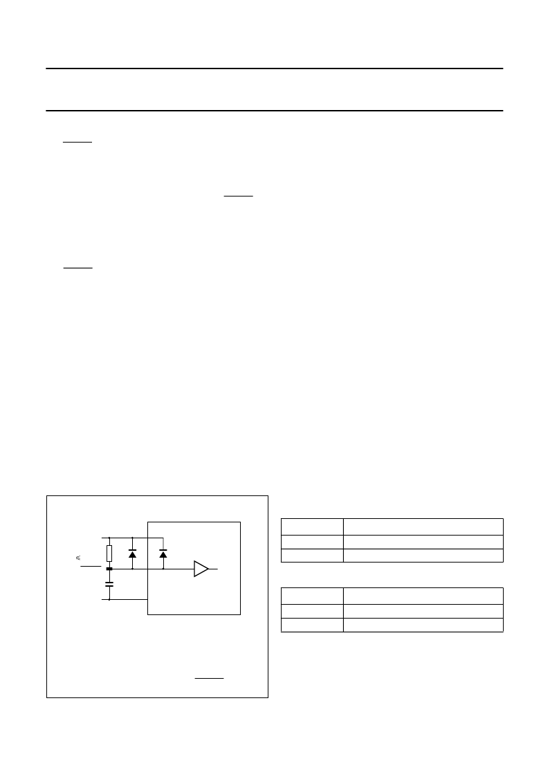
A Power-on-reset can be generated by using the
RC-circuit as shown in Fig.3.
An active reset can be generated by driving theRESET pin
from an external logic device. Such an active reset pulse
should not fall off before V
DD
has reached its
f
xtal
-dependent minimum operating voltage.
6.1
Reset trip level
The RESET trip-voltage level is masked to 1.3 V in the
PCA84C646 and PCA84C846.
6.2
Reset status
Derivative Registers status; for details see Table 40
Program Counter: 00H
Memory Bank: 00H
Register Bank: 00H
Stack Pointer: 00H
All interrupts disabled
Timer/event counter 1 stopped and cleared
Timer prescaler modulo-32 (PS = 0)
Timer flag cleared
Serial I/O interface disabled (ESO = 0) and in slave
receiver mode
Idle and Stop mode cleared.
Fig.3 External components for RESET pin.
V
(1)
V
PCA84C646/846
internal reset
R
( 100 k
)
C
MED172
DD
SS
RESET
RESET
RESET
(1) To avoid overload of the internal diode, an external
diode should be added in parallel if C
RESET
>
0.2
μ
F.
7
ANALOG CONTROL
7.1
6 and 7-bit PWM outputs (PWM00 to PWM07)
The PCA84C646/PCA84C846 has eight PWM outputs for
analog controls of e.g. volume, balance, brightness and
saturation. These PWM outputs generate pulse patterns
with a repetition rate of
1
64
×
f
PWM
or
1
128
×
f
PWM
. The
analog value is determined by the ratio of the HIGH-time
and the repetition time. A DC voltage proportional to the
PWM control setting is obtained by means of an external
integration network (low-pass filter).
The eight PWM outputs are specified as follows:
PWM00 to PWM03 outputs with 7-bit resolution
PWM04 to PWM07 outputs with 6-bit resolution.
Figure 4 shows the block diagram of the 6-bit or 7-bit PWM
DAC. The polarity of the PWM0n output is selected as
shown in Table 2 by the polarity control bit P6LVL/P7LVL
(Derivative Register 23; see Table 25).
The PWM0n output shares the pin with a DP0n I/O line
under control of a PWMnE enable bit; for selection see
Table 3.
Figure 5 shows the 6 and 7-bit PWM0n output patterns
(non-inverted; P6LVL/P7LVL = 0).
The HIGH-time of a PWM0n output is
t
HIGH
=
[
PWMnDL
] ×
t
0
where:
[
PWMnDL
]
= the contents of PWMn data latch
(n = 0 to 7; Derivative Register 10 to 17; see Table 40)
t
0
= 1/f
PWM
; f
PWM
=
1
3
×
f
xtal
.
Table 2
Polarity selection for the PWM0n output
Table 3
Selection of pin function: DP0n/PWM0n (note 1)
Note
1.
n = 0 to 7.
P6LVL/P7LVL
POLARITY
1
0
inverted
not inverted
PWMnE
FUNCTION
1
0
PWM0n output
DP0n I/O
相關(guān)PDF資料 |
PDF描述 |
|---|---|
| PCA84C886 | Microcontrollers for TV tuning control and OSD applications(應(yīng)用于TV調(diào)頻和OSD的微控制器) |
| PCA84C922 | Microcontrollers for universal infrared remote transmitter applications(應(yīng)用于通用紅外線遙控傳送的微控制器) |
| PCA8510 | On-Screen Display Circuit |
| PCA8550DR | 2-Input Digital Multiplexer |
| PCA8550D-T | 2-Input Digital Multiplexer |
相關(guān)代理商/技術(shù)參數(shù) |
參數(shù)描述 |
|---|---|
| PCA84C646P | 制造商:PHILIPS 制造商全稱:NXP Semiconductors 功能描述:Microcontrollers for TV tuning control and OSD applications |
| PCA84C64X | 制造商:未知廠家 制造商全稱:未知廠家 功能描述: |
| PCA84C822 | 制造商:PHILIPS 制造商全稱:NXP Semiconductors 功能描述:8-bit microcontrollers for remote control transmitters |
| PCA84C822A | 制造商:PHILIPS 制造商全稱:NXP Semiconductors 功能描述:8-bit microcontrollers for remote control transmitters |
| PCA84C822AP | 制造商:PHILIPS 制造商全稱:NXP Semiconductors 功能描述:8-bit microcontrollers for remote control transmitters |
發(fā)布緊急采購,3分鐘左右您將得到回復(fù)。