- 您現在的位置:買賣IC網 > PDF目錄367800 > PC755CVGU350LE (ATMEL CORP) E Core PDF資料下載
參數資料
| 型號: | PC755CVGU350LE |
| 廠商: | ATMEL CORP |
| 元件分類: | 微控制器/微處理器 |
| 英文描述: | E Core |
| 中文描述: | 32-BIT, 350 MHz, RISC PROCESSOR, CBGA360 |
| 封裝: | CERAMIC, BGA-360 |
| 文件頁數: | 21/50頁 |
| 文件大?。?/td> | 1064K |
| 代理商: | PC755CVGU350LE |
第1頁第2頁第3頁第4頁第5頁第6頁第7頁第8頁第9頁第10頁第11頁第12頁第13頁第14頁第15頁第16頁第17頁第18頁第19頁第20頁當前第21頁第22頁第23頁第24頁第25頁第26頁第27頁第28頁第29頁第30頁第31頁第32頁第33頁第34頁第35頁第36頁第37頁第38頁第39頁第40頁第41頁第42頁第43頁第44頁第45頁第46頁第47頁第48頁第49頁第50頁
21
PC755/745
2138D–HIREL–06/03
θ
jc
is the junction-to-case thermal resistance
θ
int
is the adhesive or interface material thermal resistance
θ
sa
is the heat sink base-to-ambient thermal resistance
P
d
is the power dissipated by the device
During operation the die-junction temperatures (T
j
) should be maintained less than the
value specified in Table 5. The temperature of the air cooling the component greatly
depends upon the ambient inlet air temperature and the air temperature rise within the
electronic cabinet. An electronic cabinet inlet-air temperature (T
a
) may range from 30 to
40
°
C. The air temperature rise within a cabinet (T
r
) may be in the range of 5 to 10
°
C.
The thermal resistance of the thermal interface material (
θ
int
) is typically about 1
°
C/W.
Assuming a T
a
of 30
°
C, a T
r
of 5
tion (P
d
) of 5.0 watts, the following expression for T
j
is obtained:
Die-junction temperature: T
j
= 30
°
C + 5
°
C + (0.03
°
C/W + 1.0
°
C/W +
θ
sa
) * 5.0 W
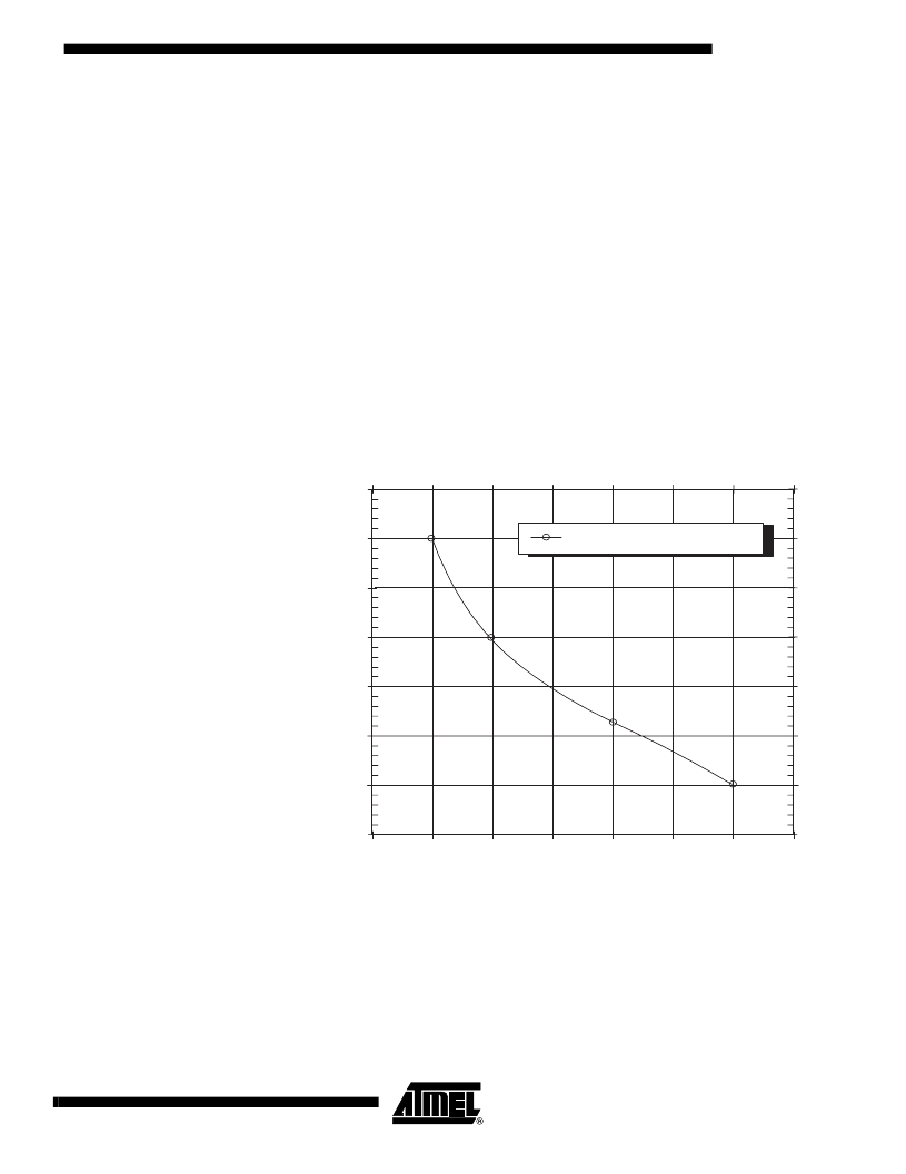
For a Thermalloy heat sink #2328B, the heat sink-to-ambient thermal resistance (
θ
sa
)
versus airflow velocity is shown in Figure 9.
o
C, a CBGA package
θ
jc
= 0.03, and a power consump-
Figure 9.
Thermalloy #2328B Heat Sink-to-Ambient Thermal Resistance Versus Air-
flow Velocity
8
Assuming an air velocity of 0.5 m/s, we have an effective R
sa
of 7
°
C/W, thus
T
j
= 30
°
C+ 5
°
C+ (0.03
°
C/W +1.0
°
C/W + 7
°
C/W) * 5.0 W,
resulting in a die-junction temperature of approximately 81
°
C which is well within the
maximum operating temperature of the component.
Other heat sinks offered by Chip Coolers, IERC, Thermalloy, Wakefield Engineering,
and Aavid Engineering offer different heat sink-to-ambient thermal resistances, and may
or may not need air flow.
1
3
5
7
0
0.5
1
1.5
2
2.5
3
3.5
Thermalloy #2328B Pin±fin Heat Sink
(25 x28 x 15 mm)
Approach Air Velocity (m/s)
2
4
6
H
相關PDF資料 |
PDF描述 |
|---|---|
| PC755CVGU366LE | E Core |
| PC755CVGU400LE | E Core |
| PC755CVGHU300LE | PowerPC 755/745 RISC Microprocessor |
| PC755CVGHU350LE | PowerPC 755/745 RISC Microprocessor |
| PC755CVGHU366LE | PowerPC 755/745 RISC Microprocessor |
相關代理商/技術參數 |
參數描述 |
|---|---|
| PC755CVGU366LE | 制造商:ATMEL 制造商全稱:ATMEL Corporation 功能描述:PowerPC 755/745 RISC Microprocessor |
| PC755CVGU400LE | 制造商:e2v technologies 功能描述:MPU RISC 32BIT 0.22UM 400MHZ 2.5V/3.3V 360CBGA - Trays |
| PC755CVZFU300LE | 制造商:ATMEL 制造商全稱:ATMEL Corporation 功能描述:PowerPC 755/745 RISC Microprocessor |
| PC755CVZFU350LE | 制造商:ATMEL 制造商全稱:ATMEL Corporation 功能描述:PowerPC 755/745 RISC Microprocessor |
| PC755CVZFU366LE | 制造商:ATMEL 制造商全稱:ATMEL Corporation 功能描述:PowerPC 755/745 RISC Microprocessor |
發(fā)布緊急采購,3分鐘左右您將得到回復。