- 您現(xiàn)在的位置:買賣IC網(wǎng) > PDF目錄383731 > OZ990S (Electronic Theatre Controls, Inc.) Intelligent Manager Smart PMU/GPIO PDF資料下載
參數(shù)資料
| 型號(hào): | OZ990S |
| 廠商: | Electronic Theatre Controls, Inc. |
| 英文描述: | Intelligent Manager Smart PMU/GPIO |
| 中文描述: | 智能管理智能電源管理單元/個(gè)GPIO |
| 文件頁數(shù): | 3/5頁 |
| 文件大小: | 39K |
| 代理商: | OZ990S |
OZ990
OZ990-SF-1.6
Page 3
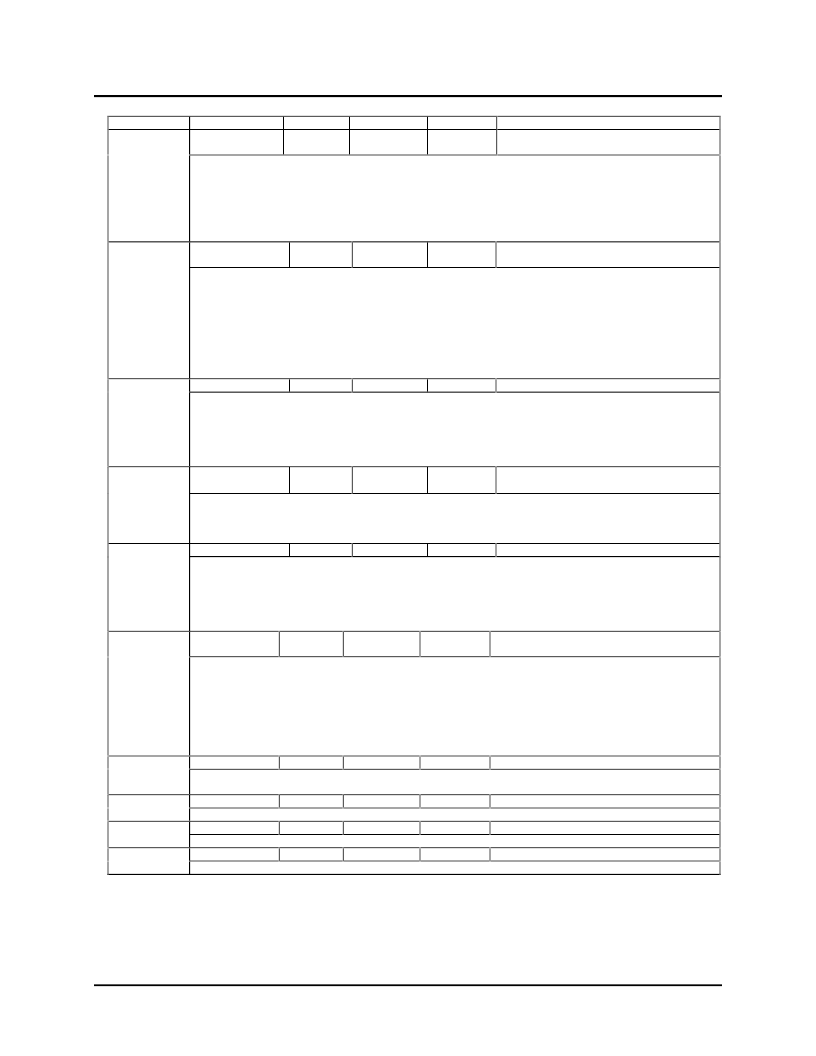
Name
Pin No.
10
Type
I/O
Input
TTL
Drive
4mA
Definition
GPIO[1]/
WAKE
General Purpose I/O /
WAKE
Fully programmable GPIO that can be used for a variety of dedicated or specific functions. Pin GPIO[1] has
WAKE output as an alternate function. GPIO[1] pin defaults as WAKE output in PMU mode, and as input in
Alternate PMU and GPIO modes. It is also programmable to function as GPI[1] input, GPO[1]output, ALF[1]
output, PWRON input, WAKE_DIS input, or ID[1] input. When implementing as ID[1] input, GPIO[1]/WAKE
pin is internally latched from external pull-ups or pull-downs, when RESETN is LOW. The values will be
stored permanently in the ID Register and GPIO[1]/WAKE pin can then be reconfigured as an output. Refer
to GPIO Config.1&2 Registers for more details and GPIO Config. Tables for input/output selections.
11
I/O
TTL
4mA
GPIO[2]/
SMBALERT#
General Purpose I/O /
SMBALERT#
Fully programmable GPIO that can be used for a variety of dedicated or specific functions. Pin GPIO[2]
defaults as input in all modes. This pin, when programmed as an alternate function, can generate the
SMBALERT# interrupt. SMBALERT# is an interrupt service request signal to the SMBus Host which can be
generated by all devices connected to the OZ990. Pin GPIO[2]/SMBALERT# is also programmable to
function as either GPI[2] input, GPO[2] output, ALF[2] output, PWRON input, WAKE_DIS input, or ID[2] input.
When implementing as ID[2] input, GPIO[2]/SMBALERT# pin is internally latched from external pull-ups or
pull-downs, when RESETN is LOW. The latched values will be stored permanently in the ID Register and
GPIO[2] pin can then be reconfigured as an output. Refer to GPIO Config.1&2 Registers for more details and
GPIO Config. Tables for I/O selections.
[13:12]
I/O
TTL
4mA
Fully programmable GPIOs that can be used for a variety of dedicated or specific functions. Pins GPIO[4:3]
default as inputs in all modes. They are programmable to function as GPI[4:3] inputs, GPO[4:3] outputs,
ALF[4:3] outputs, PWRON inputs, WAKE_DIS inputs, or ID[4:3] inputs. When implemented as ID[4:3] inputs,
GPIO[4:3] pins are internally latched from external pull-ups or pull-downs, when RESETN is LOW. The
values will be stored permanently in the ID Register. GPIO[4:3] pins can then be reconfigured as outputs.
Refer to GPIO Config.1&2 Registers for more details and GPIO Config. Tables for input/output selections.
[17:15]
I/O-U
TTL
4mA
GPIO[4:3]
General Purpose I/Os
SMBus ID Selects/
General Purpose Outputs
SMBIDSEL
[2:0]/
GPO[7:5]
Fully programmable GPIO that can be used for a variety of dedicated or specific functions. Pin
SMBIDSEL[2:0]/GPO[7:5] defaults as an input in all modes. Upon power on, when RESETN is LOW, these
pins are internally latched to determine which SMBus address is used for the OZ990. It is also programmable
to function as either GPO[7:5] or ALF[7:5] outputs.
[24:18]
I/O
TTL
4mA
Fully programmable GPIOs that can be used for a variety of dedicated or specific functions. Pins GPIO[14:8]
default as inputs in all modes. Pins GPIO[14:8] as inputs are programmable to generate SMI/SMB interrupts
and WAKE signal(pin GPIO[1]), to enter Suspend mode, or to resume Wakeup mode from Suspend
(with/without interrupt generation). They are also programmable to function as GPI[14:8] inputs, GPO[14:8]
outputs, PWRON inputs, or WAKE_DIS inputs. Refer to GPIO Config.1&2 Registers for more details and
GPIO Config. Tables for input/output selections.
25
I/O
TTL
4mA
GPIO[14:8]
General Purpose I/Os
SRBTN#/
GPIO[15]
Suspend/Resume Button /
General Purpose I/O
Fully programmable GPIO that can be used for a variety of dedicated or specific functions. In PMU mode, this
pin defaults as SRBTN# with a debounced input with
“
Wakeup
”
function triggered on the falling edge to turn
on pins PC[3:0] (PC[3:0]=1). This pin can be tied to a pushbutton to toggle between Suspend/Wakeup
modes. In Alternate PMU and GPIO modes, pin GPIO[15] defaults as input. This pin is programmable to
generate an SMB/SMI interrupt and WAKE signal(pin GPIO[1]), to enter Suspend mode, resume Wakeup
mode from Suspend (with/without interrupt generation). This pin is also programmable to function as GPI[15]
input, GPO[15] output, PWRON input, or WAKE_DIS input. Refer to GPIO Config.1&2 Registers for more
details and GPIO Config. Tables for input/output selections.
26
I
TTL
-
OZ990 hardware reset. RESETN(active LOW) resets all registers to their default values. This pin is
connected to the RC delay from the power supplied to OZ990.
27
I
TTL
-
32KHz Clock Input.
14
GND
-
-
Ground.
28
PWR
-
-
3.3V or 5V Power Supply.
RESETN
32KHz
GND
VCC
Reset
32KHz Clock Input
Ground
3.3V/5V Power Supply
相關(guān)PDF資料 |
PDF描述 |
|---|---|
| P0130AA1EA3 | 0.8A SCRs |
| P0130 | 0.8A SCRs |
| P0130AA | 0.8A SCRs |
| P0130AA2AL3 | 0.8A SCRs |
| P312XDP512F0VFV | Covers, S12XD, S12XB & S12XA Families |
相關(guān)代理商/技術(shù)參數(shù) |
參數(shù)描述 |
|---|---|
| OZ992 | 制造商:未知廠家 制造商全稱:未知廠家 功能描述:Intelligent Manager Smart ACPI GPIO/SCI |
| OZ9926 | 制造商:未知廠家 制造商全稱:未知廠家 功能描述:OZ9926電路圖 |
| OZ992S | 制造商:未知廠家 制造商全稱:未知廠家 功能描述:Intelligent Manager Smart ACPI GPIO/SCI |
| OZ9932GN | 制造商:未知廠家 制造商全稱:未知廠家 功能描述: |
| OZ9939 | 制造商:MICRO-ELECTRONICS 制造商全稱:Micro Electronics 功能描述:Updated limits for protection Release Threshold |
發(fā)布緊急采購,3分鐘左右您將得到回復(fù)。