- 您現(xiàn)在的位置:買賣IC網(wǎng) > PDF目錄383724 > ort233 (OKI SEMICONDUCTOR CO., LTD.) Reed Switch(舌簧開關(guān)) PDF資料下載
參數(shù)資料
| 型號(hào): | ort233 |
| 廠商: | OKI SEMICONDUCTOR CO., LTD. |
| 英文描述: | Reed Switch(舌簧開關(guān)) |
| 中文描述: | 干簧(舌簧開關(guān)) |
| 文件頁數(shù): | 27/145頁 |
| 文件大小: | 729K |
| 代理商: | ORT233 |
第1頁第2頁第3頁第4頁第5頁第6頁第7頁第8頁第9頁第10頁第11頁第12頁第13頁第14頁第15頁第16頁第17頁第18頁第19頁第20頁第21頁第22頁第23頁第24頁第25頁第26頁當(dāng)前第27頁第28頁第29頁第30頁第31頁第32頁第33頁第34頁第35頁第36頁第37頁第38頁第39頁第40頁第41頁第42頁第43頁第44頁第45頁第46頁第47頁第48頁第49頁第50頁第51頁第52頁第53頁第54頁第55頁第56頁第57頁第58頁第59頁第60頁第61頁第62頁第63頁第64頁第65頁第66頁第67頁第68頁第69頁第70頁第71頁第72頁第73頁第74頁第75頁第76頁第77頁第78頁第79頁第80頁第81頁第82頁第83頁第84頁第85頁第86頁第87頁第88頁第89頁第90頁第91頁第92頁第93頁第94頁第95頁第96頁第97頁第98頁第99頁第100頁第101頁第102頁第103頁第104頁第105頁第106頁第107頁第108頁第109頁第110頁第111頁第112頁第113頁第114頁第115頁第116頁第117頁第118頁第119頁第120頁第121頁第122頁第123頁第124頁第125頁第126頁第127頁第128頁第129頁第130頁第131頁第132頁第133頁第134頁第135頁第136頁第137頁第138頁第139頁第140頁第141頁第142頁第143頁第144頁第145頁
25
REED SWITCH
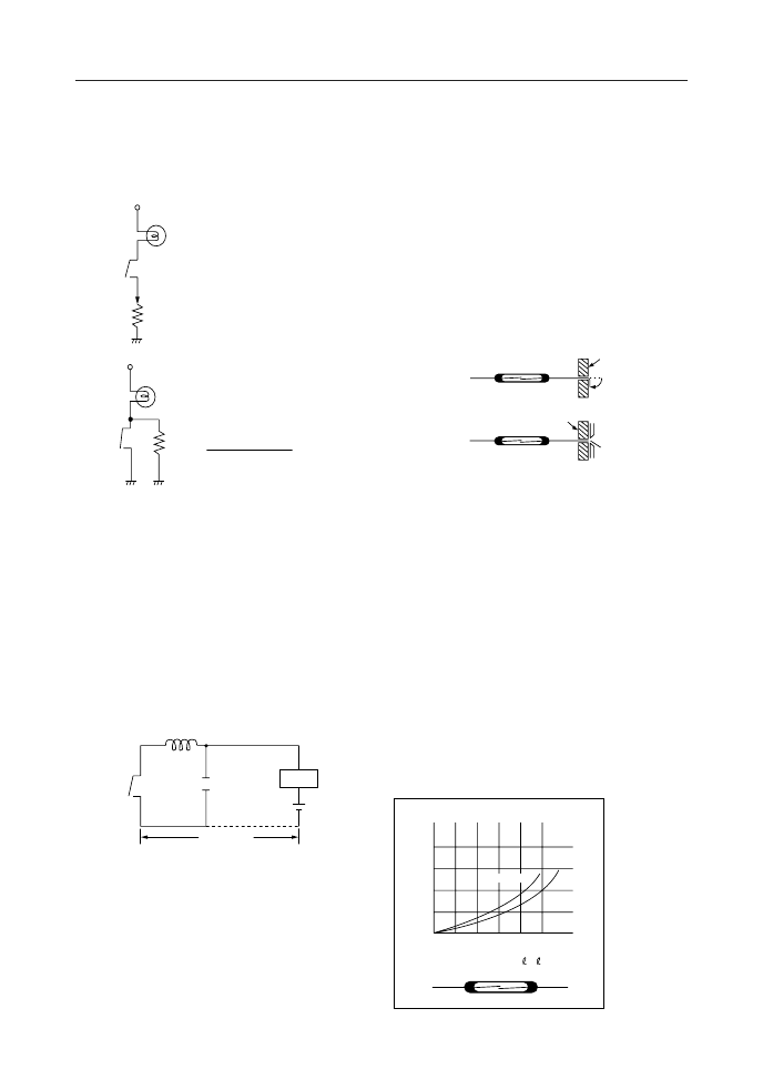
PRECAUTIONS AND APPLICATIONS
with a capacitor where large current flows
to charge the capacitor, thus requiring the
contact protection circuit. Fig. 1.3 shows
examples of protection circuits.
Figure 1.3
+E
+E
Is
R
R
R: Current limiting resistance
R should be determined to satisfy
Is < 0.5 A to 1A
R: Parallel resistance
R is put into the circuit to preheat
lamp filament and increase
the resistance. R is given by the
following.
R <Filament resistance
3
If no resistance is to be put into the circuit, use
ORD2211
1-4 Wiring capacitance
When wiring a load and reed switch over
long distance, electrostatic capacitance
arising from the cable can influence the
reed switch contact. Therefore, inductance
LS should be used. Ls value differs ac-
cording to the load current but should be
in the range of 0.5 to 5 mH.
( )
Load
Ls
Wiring
capacitance
50 m or more
2.
Reed Switch Lead Forming
When reed switches are used, usually the
leads are cut or bent. However, precau-
tions should be taken when performing
these processes.
Figure 2.2
(1) Cutting and bending positions must
be determined with reference to the
center of the contact or to the end of
the lead. If the position is measured
from the end of the glass tube, the
contact center position may be moved.
(2) When in cutting on bending the leads,
be sure to protect the sealing portions.
As shown in Figure 2.1, the lead should
be placed firmly by a jig.
(3) After the process, confirm that there is
no crack or chipping in the glass tube.
Lead bending
Lead cutting
Fixed jig
Fixed jig
Figure 2.1
2-1 Cutting the leads
Since the leads of a reed switch comprise
part of the magnetic circuit, shortening
the leads by cutting will cause the re-
quired ampere turns for pull-in and drop-
out to increase as shown in Fig. 2.2. Here
in this figure, a standard coil was used in
making measurements and there may be
differences when the reed switch is driven
by a permanent magnet depending on the
difference of the shape of magnet and
orientation of magnetization. Therefore,
it is necessary to actually examine the
change of the pull-in and drop-out values
by the magnet and drive method to be
used.
LEAD CUTTING LENGTH
1
+
2
mm
C
20
15
10
5
0
4
8
12
16
20
ORD234
ORD225
相關(guān)PDF資料 |
PDF描述 |
|---|---|
| ord2212 | Reed Switch(舌簧開關(guān)) |
| ord213 | Reed Switch(舌簧開關(guān)) |
| ord219 | Reed Switch(舌簧開關(guān)) |
| ord234 | Reed Switch(舌簧開關(guān)) |
| ORT82G5 | ORCA ORT82G5 1.0.1-25/2.0-2.5/3.125 Gbits/s Backplane Interface FPSC |
相關(guān)代理商/技術(shù)參數(shù) |
參數(shù)描述 |
|---|---|
| ORT2400 | 制造商:BOT 制造商全稱:Bedford Opto Technology Ltd. 功能描述:4 ELEMENT PCB MOUNT 1.8mm LED ARRAY |
| ORT2400B | 制造商:BOT 制造商全稱:Bedford Opto Technology Ltd. 功能描述:4 ELEMENT PCB MOUNT 1.8mm LED ARRAY |
| ORT2400BL | 制造商:BOT 制造商全稱:Bedford Opto Technology Ltd. 功能描述:4 ELEMENT PCB MOUNT 1.8mm LED ARRAY |
| ORT2400G | 制造商:BOT 制造商全稱:Bedford Opto Technology Ltd. 功能描述:4 ELEMENT PCB MOUNT 1.8mm LED ARRAY |
| ORT2400O | 制造商:BOT 制造商全稱:Bedford Opto Technology Ltd. 功能描述:4 ELEMENT PCB MOUNT 1.8mm LED ARRAY |
發(fā)布緊急采購,3分鐘左右您將得到回復(fù)。