- 您現(xiàn)在的位置:買賣IC網(wǎng) > PDF目錄383700 > OPE5685 (Electronic Theatre Controls, Inc.) High Speed GaAlAs Infrared Emitter PDF資料下載
參數(shù)資料
| 型號: | OPE5685 |
| 廠商: | Electronic Theatre Controls, Inc. |
| 英文描述: | High Speed GaAlAs Infrared Emitter |
| 中文描述: | 高速紅外發(fā)射器的GaAIAs |
| 文件頁數(shù): | 1/2頁 |
| 文件大小: | 185K |
| 代理商: | OPE5685 |
7
High Speed GaAlAs Infrared Emitter
OPE5685
The
OPE5685
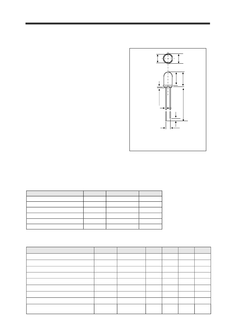
is GaAlAs infrared emitting diode DIMENSIONS
(Unit : mm)
that is designed for high power, low forward voltage
and high speed rise / fall time.
This device is optimized for speed and efficiency
at emission wavelength 850nm and has a high radiant
efficiency over a wide range of forward current.
This device is packaged T1-3/4 plastic package
and has wide beam angle with lensed package
and cup frame. Especially this device is suited
as the emitter of data transmission without cable.
FEATURES
High speed : 25ns rise time
850nm wavelength
Wide beam angle
Low forward voltage
High power and high reliability
Available for pulse operating
APPLICATIONS
Emitter of IrDA
IR Audio and Telephone
High speed IR communication
IR LANs
Available for wireless digital data transmission
STORAGE
Condition : 5
°
C~35
°
C,R.H.60%
Terms : within 3 months from production date
Remark : Once the package is opened, the products should be used within a day.
Otherwise, it should be keeping in a damp proof box with desiccants.
* Please take proper steps in order to secure reliability and safety in required conditions
and environments for this device.
MAXIMUM RATINGS
Item
Symbol
Power Dissipation
P
D
Forward current
I
F
Pulse forward current
Reverse voltage
V
R
Operating temp.
Topr.
Soldering temp.
*2
Tsol.
*1
.Duty ratio = 1/100, pulse width=0.1ms.
*2
.Lead Soldering Temperature (2
mm
from case for 5sec.).
ELECTRO-OPTICAL CHARACTERISTICS
Item
Symbol
Forward voltage
V
F
Reverse current
I
R
Capacitance
Ct
Radiant intensity
Ie
Peak emission wavelength
λ
p
Spectral bandwidth 50%
λ
Half angle
θ
Optical rise & fall time(10%~90%)
tr/tf
(Ta=25
°
C)
Rating
150
100
1.0
4.0
-25~ +85
260
.
Unit
MW
MA
A
V
°
C
°
C
I
FP
(Ta=25
°
C)
Conditions
Min.
I
F
=50mA
V
R
=4V
f=1
MHz
I
F
=50mA
I
F
=50mA
I
F
=50mA
I
F
=50mA
I
F
=50mA
25/13
I
F
=50mA DC
+10mA p-p
Typ.
1.5
20
50
850
45
±
22
Max.
2.0
10
Unit
V
μ
A
pF
mW/sr
nm
nm
deg.
ns
Cut off frequency
*3
fc
14
MHz
*3
. 10logPo(fc
MHz
)/Po(0.1
MHz
)=-3
2-
0.5
2
2.5
2
Anode
Cathode
8
7
1
5
5
Tolerance :
±
0.2mm
相關(guān)PDF資料 |
PDF描述 |
|---|---|
| OPE5687HP | High Speed GaAIAs Infrared Emitter |
| OPE5794 | GaAlAs Infrared Emitter |
| OPERATIONMODE | EM73201/EM73E00/EM73PE00 Application Note |
| OPF1402T | 1A Low Voltage Low lq LDO, -40C to +125C, 8-SOIC 150mil, T/R |
| OPF1404T | 1A Low Voltage Low lq LDO, -40C to +125C, 8-DFN, T/R |
相關(guān)代理商/技術(shù)參數(shù) |
參數(shù)描述 |
|---|---|
| OPE5687HP | 制造商:未知廠家 制造商全稱:未知廠家 功能描述:High Speed GaAIAs Infrared Emitter |
| OPE5794 | 制造商:OPTEK 制造商全稱:OPTEK 功能描述:GaAlAs Infrared Emitter |
| OPE5885 | 制造商:未知廠家 制造商全稱:未知廠家 功能描述:DHigh Speed GaAlAs Infrared Emitter |
| OPE5985 | 制造商:未知廠家 制造商全稱:未知廠家 功能描述:High Speed GaAlAs Infrared Emitter |
| OPE5T62UO | 制造商:未知廠家 制造商全稱:未知廠家 功能描述:AIGaInP Ultra Bright Orange LED Lamp |
發(fā)布緊急采購,3分鐘左右您將得到回復(fù)。