- 您現(xiàn)在的位置:買(mǎi)賣(mài)IC網(wǎng) > PDF目錄299560 > NRLM332M50V20X40F (NIC Components Corp.) Large Can Aluminum Electrolytic Capacitors PDF資料下載
參數(shù)資料
| 型號(hào): | NRLM332M50V20X40F |
| 廠(chǎng)商: | NIC Components Corp. |
| 英文描述: | Large Can Aluminum Electrolytic Capacitors |
| 中文描述: | 大型鋁電解電容器能 |
| 文件頁(yè)數(shù): | 1/3頁(yè) |
| 文件大?。?/td> | 67K |
| 代理商: | NRLM332M50V20X40F |
144
NIC COMPONENTS CORP.
www.niccomp.com
www.lowESR.com
www.RFpassives.com
www.SMTmagnetics.com
Large Can Aluminum Electrolytic Capacitors
FEATURES
NEW SIZES FOR LOW PROFILE AND HIGH DENSITY DESIGN OPTIONS
EXPANDED CV VALUE RANGE
HIGH RIPPLE CURRENT
LONG LIFE
CAN-TOP SAFETY VENT
DESIGNED AS INPUT FILTER OF SMPS
STANDARD 10mm (.400") SNAP-IN SPACING
NRLM Series
SPECIFICATIONS
(* 47,000
F add 0.14, 68,000F add 0.35.)
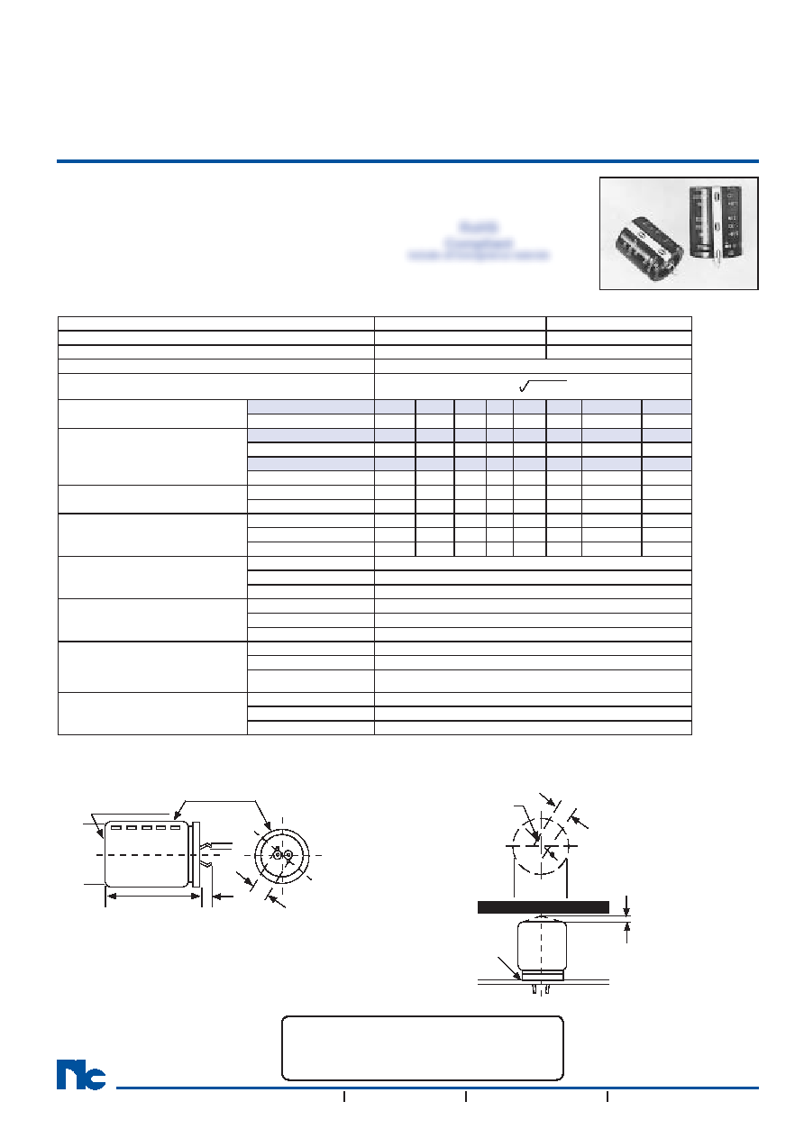
Notice for Mounting
The space from the top of the can shall be more than (3mm)
from chassis or other construction materials so that safety
vent has room to expand in case of emergency.
Sleeve Color: Dark
Blue
Can Top Safety Vent
Insulation Sleeve and
Minus Polarity Marking
(4.0mm Leads Available As Option)
D+1
Max.
L
± 2
6.3
± 1
0.8
10
(-)
(+)
MAXIMUM EXPANSION
FOR SAFETY VENT
Approx.
3.0mm
Recommended PC Board Mounting Holes:
10
± .1
= 2 ± 0.1
D
± 0.5
Chassis
PC Board
PRECAUTIONS
Please review the notes on correct use, safety and precautions found on pages T10 & T11
of NIC’s Electrolytic Capacitor catalog.
Also found at www.niccomp.com/precautions
If in doubt or uncertainty, please review your specic application - process details with
NIC’s technical support personnel: tpmg@niccomp.com
Operating Temperature Range
-40 ~ +85°C
-25 ~ +85°C
Rated Voltage Range
16 ~ 250Vdc
350 ~ 450Vdc
Rated Capacitance Range
180 ~ 68,000
F
56 ~ 680
F
Capacitance Tolerance
±20% (M)
Max. Leakage Current (
A)
After 5 minutes (20°C)
3 x
C(
F)V
Max. Tan
δ
at 120Hz/20°C
W.V. (Vdc)
16
25
35
50
63
80
100
160~450
Tan
δ max.
0.50*
0.40*
0.35 0.30 0.25
0.20
0.15
Surge Voltage
W.V. (Vdc)
16
25
35
50
63
80
100
160
S.V. (Vdc)
20
32
44
63
79
100
125
200
W.V. (Vdc)
180
200
250
350
400
450
-
S.V. (Vdc)
220
250
300
400
450
500
-
Ripple Current
Correction Factors
Frequency (Hz)
50
60
100
120
500
1K
10K ~ 50K
-
Multiplier at 85°C
0.75
0.80
0.95 1.00 1.05
1.08
1.15
-
Low Temperature
Stability (10 to 250Vdc)
Temperature (°C)
0
-25
-40
-
Capacitance Change
-5%
-15%
-30%
-
Impedance Ratio
1.5
3
9
-
Load Life Test
2,000 hours at +85°C
Capacitance Change
Within ±20% of initial measured value
Tan
δ
Less than 200% of specied maximum value
Leakage Current
Less than specied maximum value
Shelf Life Test
1,000 hours at +85°C
(no load)
Capacitance Change
Within ±20% of initial measured value
Tan
δ
Less than 200% of specied maximum value
Leakage Current
Less than specied maximum value
Surge Voltage Test
Per JIS-C-5141 (table #6, #4)
Surge voltage applied: 30 seconds
"On" and 5.5 minutes no voltage "Off"
Capacitance Change
Within ±20% of initial measured value
Tan
δ
Less than 200% of specied maximum value
Leakage Current
Less than specied maximum value
Soldering Effect
Refer to
MIL-STD-202F Method 210A
Capacitance Change
Within ±10% of initial measured value
Tan
δ
Less than specied maximum value
Leakage Current
Less than specied maximum value
RoHS
Compliant
includes all homogeneous materials
*See Part Number System for Details
相關(guān)PDF資料 |
PDF描述 |
|---|---|
| NRLM332M50V22X35F | Large Can Aluminum Electrolytic Capacitors |
| NRLM332M50V22X45F | Large Can Aluminum Electrolytic Capacitors |
| NSG41270A | 70 A, 1200 V, N-CHANNEL IGBT, TO-258 |
| NSP5251 | 150 V, NPN, Si, POWER TRANSISTOR, TO-258 |
| NSR4R7M50V6.3X5TBF | Miniature Aluminum Electrolytic Capacitors |
相關(guān)代理商/技術(shù)參數(shù) |
參數(shù)描述 |
|---|---|
| NRLM332M50V22X30F | 制造商:NIC Components Corp 功能描述: 制造商:NIC Components Corp 功能描述:AL LYTIC,SNAP-IN,.0033UF,20%,50V,-40+85,BULK,HAZMAT - Bulk |
| NRLM332M50V22X35F | 制造商:NIC 制造商全稱(chēng):NIC-Components Corp. 功能描述:Large Can Aluminum Electrolytic Capacitors |
| NRLM332M50V22X45F | 制造商:NIC 制造商全稱(chēng):NIC-Components Corp. 功能描述:Large Can Aluminum Electrolytic Capacitors |
| NRLM332M50V25X25F | 制造商:NIC Components Corp 功能描述:- Bulk |
| NRLM332M50V25X30F | 制造商:NIC 制造商全稱(chēng):NIC-Components Corp. 功能描述:Large Can Aluminum Electrolytic Capacitors |
發(fā)布緊急采購(gòu),3分鐘左右您將得到回復(fù)。