- 您現(xiàn)在的位置:買賣IC網 > PDF目錄382352 > MTV030 (Electronic Theatre Controls, Inc.) On-Screen Display with Auto-Sizing Controller PDF資料下載
參數(shù)資料
| 型號: | MTV030 |
| 廠商: | Electronic Theatre Controls, Inc. |
| 英文描述: | On-Screen Display with Auto-Sizing Controller |
| 中文描述: | 屏幕顯示與自動上漿控制器 |
| 文件頁數(shù): | 4/21頁 |
| 文件大小: | 372K |
| 代理商: | MTV030 |
4/21
MTV030 Revision 1.0 10/15/1999
MTV030
MYSON
TECHNOLOGY
3.0 FUNCTIONAL DESCRIPTIONS
3.1 SERIAL DATA INTERFACE
The serial data interface receives data transmitted from an external controller. And there are 2 types of bus
can be accessed through the serial data interface, one is SPI bus and other is I
2
C bus.
3.1.1 SPI bus
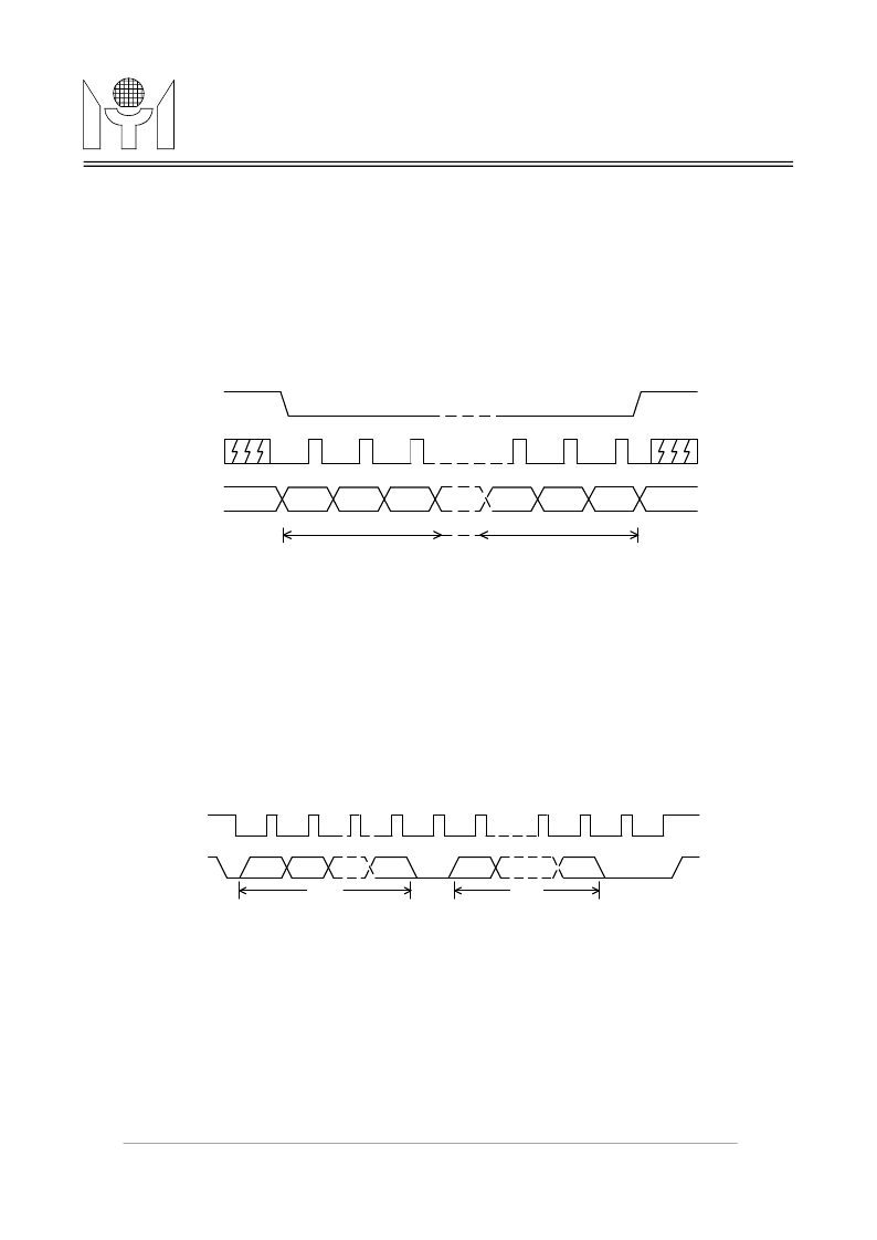
While SSB pin is pulled to "high" or "low" level, the SPI bus operation is selected. And a valid transmission
should be starting from pulling SSB to "low" level, enabling MTV030 to receiving mode, and retain "low" level
until the last cycle for a complete data packet transfer. The protocol is shown in Figure 1.
There are three transmission formats shown as below:
Format (a) R - C - D
→
R - C - D
→
R - C - D .....
Format (b) R - C - D
→
C - D
→
C - D
→
C - D .....
Format (c) R - C - D
→
D
→
D
→
D
→
D
→
D .....
Where R=Row address, C=Column address, D=Display data
3.1.2 I
2
C bus
I
2
C bus operation is only selected when SSB pin is left floating. And a valid transmission should be starting
from writing the slave address 7AH(write mode), or 7BH(read mode) to MTV030. The protocol is shown in
Figure 2. And the auto sizing video measurement data (total 10 bytes) are read only registers and the others
are write only registers.
There are three transmission formats for I
2
C write mode shown as below:
Format (a) S - R - C - D
→
R - C - D
→
R - C - D .....
Format (b) S - R - C - D
→
C - D
→
C - D
→
C - D .....
Format (c) S - R - C - D
→
D
→
D
→
D
→
D
→
D .....
Where S=Slave address, R=Row address, C=Column address, D=Display data
And there is one transmission format for I
2
C read mode shown as below:
Format (a) S
→
D
→
D
→
D
→
D
→
D
→
D
→
D
→
D
→
D
→
D
→
dummy D
→
dummy D .....
Where S=Slave address, D=Measurement data
MSB
LSB
SSB
SCK
SDA
first byte
last byte
FIGURE 1. Data Transmission Protocol (SPI)
FIGURE 2. Data Transmission Protocol (I
2
C)
SCK
SDA
first byte
START
ACK
second byte
last byte
ACK
STOP
B7
B6
B0
B7
B0
相關PDF資料 |
PDF描述 |
|---|---|
| MTV112M | 8051 Embedded CRT Monitor Controller Flash Version |
| MTV118 | On-Screen-Display for LCD Monitor |
| MTV121 | Super On-Screen-Display for LCD Monitor |
| MUA08A | 265mW at 3.3V Supply Audio Power Amplifier with Shutdown Mode |
| MUB08A | 1W, Bypass-Capacitor-less Audio Amplifier with Internal Selectable Gain |
相關代理商/技術參數(shù) |
參數(shù)描述 |
|---|---|
| MTV038 | 制造商:未知廠家 制造商全稱:未知廠家 功能描述:On-Screen Display Controller for CRT/LCD Monitor |
| MTV038N | 制造商:未知廠家 制造商全稱:未知廠家 功能描述:On-Screen Display Controller for CRT/LCD Monitor |
| MTV038N20 | 制造商:未知廠家 制造商全稱:未知廠家 功能描述:On-Screen Display Controller for CRT/LCD Monitor |
| MTV048 | 制造商:未知廠家 制造商全稱:未知廠家 功能描述:On-Screen-Display Controller for CRT/LCD Monitor |
| MTV-10-250L | 制造商:3M Electronic Products Division 功能描述:Highland(TM) Vinyl Insulated Male Tab MTV10-250L, 12-10 AWG |
發(fā)布緊急采購,3分鐘左右您將得到回復。