- 您現(xiàn)在的位置:買賣IC網(wǎng) > PDF目錄383646 > MT933 (Mitel Networks Corporation) () PDF資料下載
參數(shù)資料
| 型號: | MT933 |
| 廠商: | Mitel Networks Corporation |
| 英文描述: | () |
| 中文描述: | () |
| 文件頁數(shù): | 3/6頁 |
| 文件大?。?/td> | 38K |
| 代理商: | MT933 |

Application Note
MSAN-182
3
the TX pair is determined by the type of magnetic
you choose for your design. We suggest a magnetic
with a 1:1 ratio on the RX pair and a ratio of 1:
√
2 on
the TX pair. The recommended transformer is the
Pulse H1119. This provides effective coupling to the
Network by matching the impedance of the traces to
the impedance of the cable.
The RX termination resistors should be located as
close to the pins as possible.
3.0
CardBus Applications
When implementing the MT933 into applications
where the board area is limited, such as CardBus
Applications, alternative methods for splitting the
TXVDD
and
RXVDD
power
planes
may
be
recommended. If the VDD islands created have an
area of much less than 1 square inch, the planar
properties are lost and the planes should be joined
together to form a single Analog VDD (AVDD) plane.
4.0
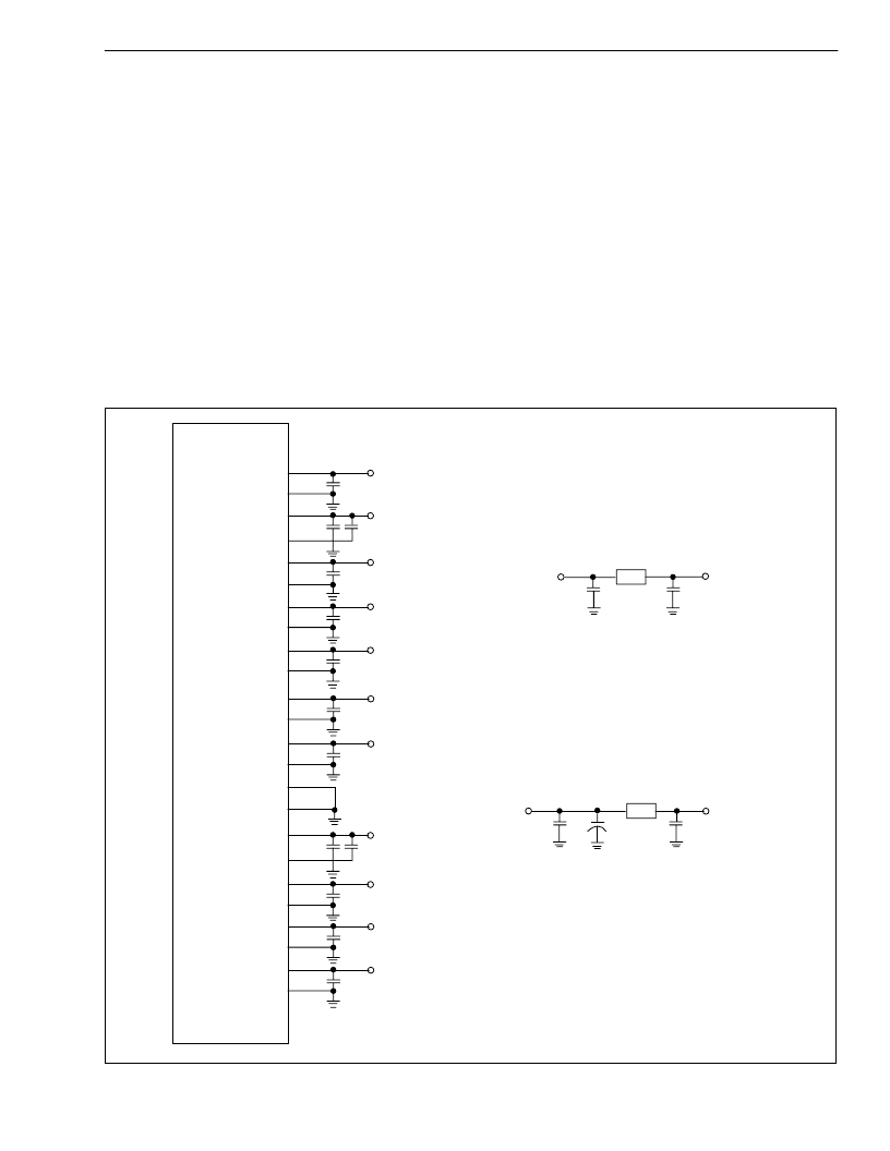
Power Supply Decoupling
Decoupling of power supplies is very important to
help ensure the success of the design. Values for the
decoupling components are shown in the schematic
diagram. The values, locations, and number of
components
shown
represent
conditions for the MT933. Based on your application
alternative decoupling schemes may be necessary,
including less decoupling or different component
values.
known
working
Figure 2 - Pin and Power Rail Capacitor Decoupling
DVDD1
DGND1
DVDD2
DGND2
DVDD3
DGND3
OSCVDD
OSCGND
RXVDD3
RXGND3
RXVDD2
RXGND2
RXVDD1
RXGND1
SUBGND
SUBGND
TXVDD1
TXGND1
TXVDD2
TXGND2
TXVDD3
TXGND3
TXVDD4
TXGND4
MT933
.01
μ
f
+3.3V
FB
FB
+3.3V
+3.3V
+3.3V
RXVDD
RXVDD
RXVDD
Tf
TXVDD
TXVDD
TXVDD
.01
μ
f
8
3
54
52
47
44
42
39
9
10
15
16
21
18
32
1
27
.1
μ
f
26
24
25
34
33
37
38
.1
μ
f
.001
μ
f
.01
μ
f
.01
μ
f
.01
μ
f
.01
μ
f
.001
.01
μ
f
.01
μ
f
.01
μ
f
.01
μ
f
6.8
μ
f
.01
μ
f
.01
μ
f
.01
μ
f
+3.3V
+3.3V
TXVDD
RXVDD
相關(guān)PDF資料 |
PDF描述 |
|---|---|
| MT93L16 | Low-Voltage Acoustic Echo Canceller(低電壓回聲消除器) |
| MTD2955V-1 | 30V N-Channel PowerTrench MOSFET |
| MTD2955V-1G | 30V N-Channel PowerTrench MOSFET |
| MTD2955VG | 30V N-Channel PowerTrench MOSFET |
| MTD2955VT4 | 30V N-Channel PowerTrench MOSFET |
相關(guān)代理商/技術(shù)參數(shù) |
參數(shù)描述 |
|---|---|
| MT933CG | 制造商:ZARLINK 制造商全稱:Zarlink Semiconductor Inc 功能描述:3.3V 10/100 Fast Ethernet Transceiver to MII |
| MT933TP1N | 制造商:ZARLINK 制造商全稱:Zarlink Semiconductor Inc 功能描述:3.3V 10/100 Fast Ethernet Transceiver to MII |
| MT938T17K26S001 | 制造商:Matrix 功能描述:Connector |
| MT938T17K26S-001 | 制造商:Matrix 功能描述:Connector |
| MT93L00A | 制造商:ZARLINK 制造商全稱:Zarlink Semiconductor Inc 功能描述:Multi-Channel Voice Echo Canceller |
發(fā)布緊急采購,3分鐘左右您將得到回復(fù)。