- 您現(xiàn)在的位置:買賣IC網(wǎng) > PDF目錄359235 > MT9300B (Zarlink Semiconductor Inc.) Multi-Channel Voice Echo Canceller PDF資料下載
參數(shù)資料
| 型號: | MT9300B |
| 廠商: | Zarlink Semiconductor Inc. |
| 英文描述: | Multi-Channel Voice Echo Canceller |
| 中文描述: | 多通道語音回聲消除器 |
| 文件頁數(shù): | 16/39頁 |
| 文件大小: | 629K |
| 代理商: | MT9300B |
第1頁第2頁第3頁第4頁第5頁第6頁第7頁第8頁第9頁第10頁第11頁第12頁第13頁第14頁第15頁當(dāng)前第16頁第17頁第18頁第19頁第20頁第21頁第22頁第23頁第24頁第25頁第26頁第27頁第28頁第29頁第30頁第31頁第32頁第33頁第34頁第35頁第36頁第37頁第38頁第39頁
MT9300B
Data Sheet
16
Zarlink Semiconductor Inc.
Memory Mapped Control and Status registers
Internal memory and registers are memory mapped into the address space of the HOST interface. The internal dual
ported memory is mapped into segments on a “per channel” basis to monitor and control each individual echo
canceller and associated PCM channels. For example, in
Normal configuration
, echo canceller #5 makes use of
Echo Canceller B from group 2. It occupies the internal address space from 0A0h to 0BFh and interfaces to PCM
channel #5 on all serial PCM I/O streams.
As illustrated in Figure 8, the “per channel” registers provide independent control and status bits for each echo canceller.
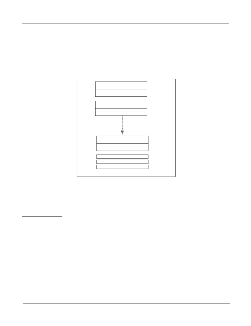
Figure 9 shows the memory map of the control/status register blocks for all echo cancellers.
Figure 9 - Memory Mapping
When
Extended Delay
or
Back-to-Back
configuration is selected, Control Register A1/B1 and Control Register 2
of the selected group of echo cancellers require special care. Refer to the Register description section.
Table 2 is a list of the channels used for the 16 groups of echo cancellers when they are configured as
Extended
Delay
or
Back-to-Back
Normal Configuration
For a given group (group 0 to 15), 2 PCM I/O channels are used. For example, group 1 Echo Cancellers A and B,
channels 2 and 3 are active.
0000H -->
Channel 0, EC A Ctrl/Stat Registers
001FH
0020H -->
Channel 1, EC B Ctrl/Stat Registers
003FH
0040H -->
Channel 2, EC A Ctrl/Stat Registers
005FH
0060H -->
Channel 3, EC B Ctrl/Stat Registers
007FH
03C0H -->
Channel 30, EC A Ctrl/Stat Registers
03DFH
03E0H -->
Channel 31, EC B Ctrl/Stat Registers
03FFH
0400H --> 040FH
Main Control Registers <15:0>
Group 0
Echo
Cancellers
Registers
Groups 2 --> 14
Echo Cancellers
Registers
Group 1
Echo
Cancellers
Registers
Group 15
Echo
Cancellers
Registers
0410H
Interrupt FIFO Register
0411H
Test Register
相關(guān)PDF資料 |
PDF描述 |
|---|---|
| MT9300BL | Multi-Channel Voice Echo Canceller |
| MT9300BV | Multi-Channel Voice Echo Canceller |
| MT9315 | CMOS Acoustic Echo Canceller |
| MT933 | 3.3V 10/100 Fast Ethernet Transceiver to MII |
| MT933CG | 3.3V 10/100 Fast Ethernet Transceiver to MII |
相關(guān)代理商/技術(shù)參數(shù) |
參數(shù)描述 |
|---|---|
| MT9300BL | 制造商:ZARLINK 制造商全稱:Zarlink Semiconductor Inc 功能描述:Multi-Channel Voice Echo Canceller |
| MT9300BV | 制造商:ZARLINK 制造商全稱:Zarlink Semiconductor Inc 功能描述:Multi-Channel Voice Echo Canceller |
| MT9315 | 制造商:ZARLINK 制造商全稱:Zarlink Semiconductor Inc 功能描述:CMOS Acoustic Echo Canceller |
| MT9315AE | 制造商:ZARLINK 制造商全稱:Zarlink Semiconductor Inc 功能描述:CMOS Acoustic Echo Canceller |
| MT9315AP | 制造商:ZARLINK 制造商全稱:Zarlink Semiconductor Inc 功能描述:CMOS Acoustic Echo Canceller |
發(fā)布緊急采購,3分鐘左右您將得到回復(fù)。