- 您現(xiàn)在的位置:買賣IC網(wǎng) > PDF目錄383645 > MT9075BP (Mitel Networks Corporation) E1 Single Chip Transceiver PDF資料下載
參數(shù)資料
| 型號: | MT9075BP |
| 廠商: | Mitel Networks Corporation |
| 英文描述: | E1 Single Chip Transceiver |
| 中文描述: | 素E1單芯片收發(fā)器 |
| 文件頁數(shù): | 4/78頁 |
| 文件大?。?/td> | 1008K |
| 代理商: | MT9075BP |
第1頁第2頁第3頁當前第4頁第5頁第6頁第7頁第8頁第9頁第10頁第11頁第12頁第13頁第14頁第15頁第16頁第17頁第18頁第19頁第20頁第21頁第22頁第23頁第24頁第25頁第26頁第27頁第28頁第29頁第30頁第31頁第32頁第33頁第34頁第35頁第36頁第37頁第38頁第39頁第40頁第41頁第42頁第43頁第44頁第45頁第46頁第47頁第48頁第49頁第50頁第51頁第52頁第53頁第54頁第55頁第56頁第57頁第58頁第59頁第60頁第61頁第62頁第63頁第64頁第65頁第66頁第67頁第68頁第69頁第70頁第71頁第72頁第73頁第74頁第75頁第76頁第77頁第78頁
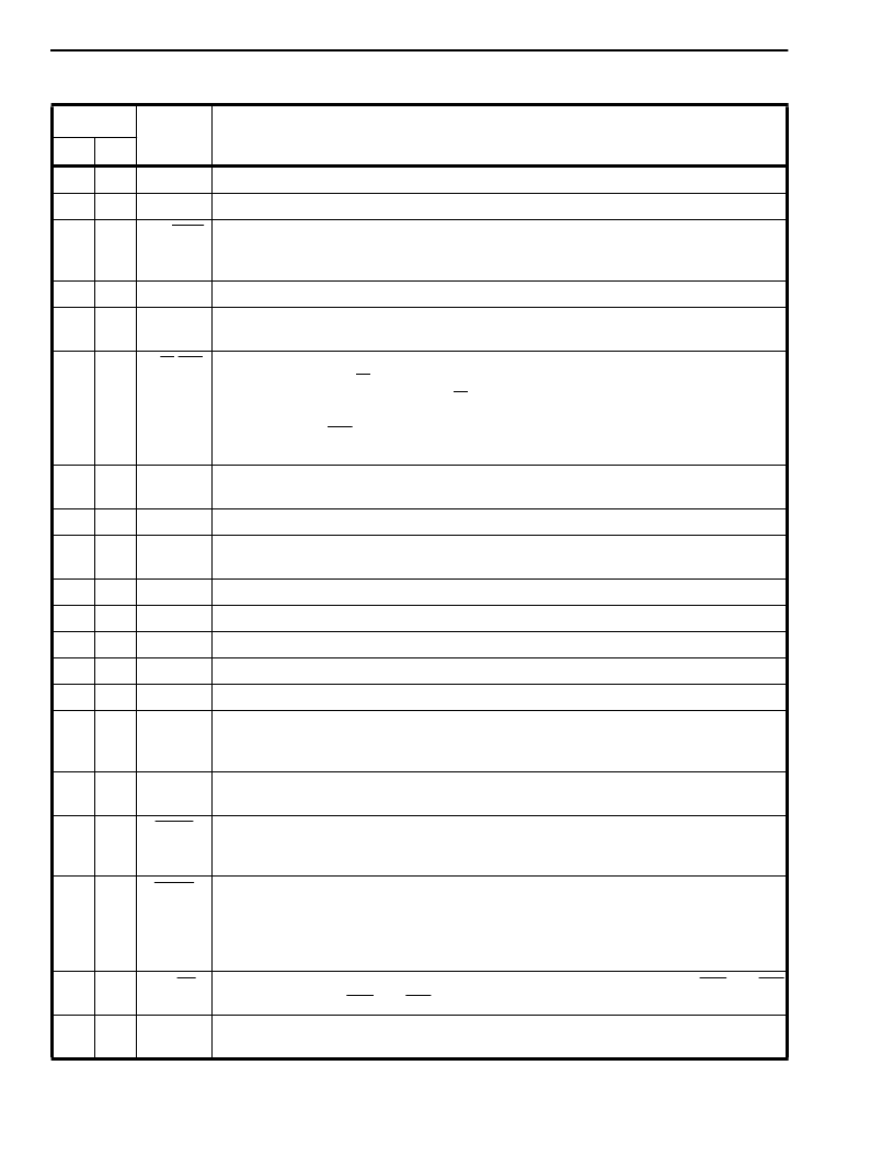
MT9075A
Preliminary Information
4-132
17
90
VSS
Negative Power Supply (Input).
Digital ground.
18
91
IC
Internal Connection.
Tie to V
SS
(Ground) for normal operation.
INT/MOT Intel/Motorola Mode Selection (Input).
A high on this pin configures the processor
interface for the Intel parallel non-multiplexed bus type. A low configures the processor
interface for the Motorola parallel non-multiplexed type.
19
92
20
93
VDD
Positive Power Supply (Input).
Digital supply (+5V
±
5%).
21 -
24
94-
97
D4 - D7
Data 4 to Data 7 (Three-state I/O).
These signals combined with D0-D3 form the
bidirectional data bus of the microprocessor interface (D7 is the most significant bit).
25
98
R/W/WR Read/Write/Write Strobe (Input).
In Motorola mode (R/W), this input controls the direction of the data bus D[0:7] during
a microprocessor access. When R/W is high, the parallel processor is reading data
from the MT9075A. When low, the microprocessor is writing data to the MT9075A.
For Intel mode (WR), this active low write strobe configures the data bus lines as
output.
26 -
30
99,
8-11
AC0 -
AC4
Address/Control 0 to 4 (Inputs).
Address and control inputs for the microprocessor
interface. AC0 is the least significant input.
31
12
GNDARx Receive Analog Ground (Input).
Analog ground for the LIU receiver.
32
33
13
14
RTIP
RRING
Receive TIP and RING (Inputs).
Differential inputs for the receive line signal - must be
transformer coupled (See Figure 4).
34
15
VDDARx Receive Analog Power Supply (Input).
Analog supply for the LIU receiver (+5V
±
5%).
Positive Power Supply (Input).
Digital supply (+5V
±
5%).
35
16
VDD
36
17
VSS
Negative Power Supply (Input).
Digital ground.
37
18
IC
Internal Connection.
Must be left open for normal operation.
38
19
IC
Internal Connection.
Must be left open for normal operation.
39
20
RxDLCLK Receive Data Link Clock (Output)
. A gapped clock signal derived from a 2.048 Mbit/s
clock, available for an external device to clock in RxDL data (at 4, 8, 12, 16 or 20 kHz) on
the rising edge.
40
21
RxDL
Receive Data Link (Output)
. A 2.048 Mbit/s data stream containing received line data
after HDB3 decoding. This data is clocked out with the rising edge of E2o.
41
22
TxMF
Transmit Multiframe Boundary (Input)
. An active low input used to set the transmit
multiframe boundary (CAS or CRC multiframe). The MT9075A will generate its own
multiframe if this pin is held high. This input is usually pulled high for most applications.
42
23
RxMF
Receive Multiframe Boundary (Output).
An output pulse delimiting the received
multiframe boundary. The next frame output on the data stream (DSTo) is basic frame
zero on the PCM 30 link. This receive multiframe signal can be related to either the
receive CRC multiframe (page 01H, address 10H, bit 6, MFSEL=1) or the receive
signalling multiframe (MFSEL=0).
43
24
BS/LS
System Bus Synchronous/Line Synchronous Selection (Input)
. If high, C4b and F0b
will be inputs; if low, C4b and F0b will be outputs.
44
32
E2o
2.048 MHz Extracted Clock (Output).
The clock extracted from the received signal
and used internally to clock in data received on RTIP and RRING.
Pin Description (continued)
Pin #
Name
Description
PLCC MQFP
相關PDF資料 |
PDF描述 |
|---|---|
| MT9075B-1 | E1 Single Chip Transceiver |
| MT9075 | () |
| MT9076 | T1/E1/J1 3.3V Single Chip Transceiver |
| MT9076AB | T1/E1/J1 3.3V Single Chip Transceiver |
| MT9076 | T1/E1/J1 3.3V Single Chip Transceiver(T1/E1/J1 3.3V 單片收發(fā)器) |
相關代理商/技術參數(shù) |
參數(shù)描述 |
|---|---|
| MT9075BP1 | 制造商:Microsemi Corporation 功能描述:Single Chip Transceiver 1TX 1RX 2.048Mbps 68-Pin PLCC Tube 制造商:Microsemi Corporation 功能描述:FRAMER E1 5V 68PLCC - Rail/Tube 制造商:Microsemi Corporation 功能描述:PB FREE E1 SINGLE CHIP TRANSCEIVER 制造商:MICROSEMI CONSUMER MEDICAL PRODUCT GROUP 功能描述:IC TXRX SGL E1 W/LIU 68PLCC 制造商:Microsemi Corporation 功能描述:IC TXRX SGL E1 W/LIU 68PLCC |
| MT9075BPR | 制造商:ZARLINK 制造商全稱:Zarlink Semiconductor Inc 功能描述:E1 Single Chip Transceiver |
| MT9075BPR1 | 制造商:Microsemi Corporation 功能描述:FRAMER E1 5V 68PLCC - Tape and Reel |
| MT9076 | 制造商:MITEL 制造商全稱:Mitel Networks Corporation 功能描述:T1/E1/J1 3.3V Single Chip Transceiver |
| MT9076AB | 制造商:MITEL 制造商全稱:Mitel Networks Corporation 功能描述:T1/E1/J1 3.3V Single Chip Transceiver |
發(fā)布緊急采購,3分鐘左右您將得到回復。