- 您現(xiàn)在的位置:買賣IC網(wǎng) > PDF目錄383642 > MT88L89AE (Mitel Networks Corporation) 3V Integrated DTMFTransceiver with Adaptive Micro Interface PDF資料下載
參數(shù)資料
| 型號: | MT88L89AE |
| 廠商: | Mitel Networks Corporation |
| 英文描述: | 3V Integrated DTMFTransceiver with Adaptive Micro Interface |
| 中文描述: | 3V的綜合DTMFTransceiver自適應(yīng)微型接口 |
| 文件頁數(shù): | 7/20頁 |
| 文件大?。?/td> | 352K |
| 代理商: | MT88L89AE |
Advance Information
MT88L89
4-131
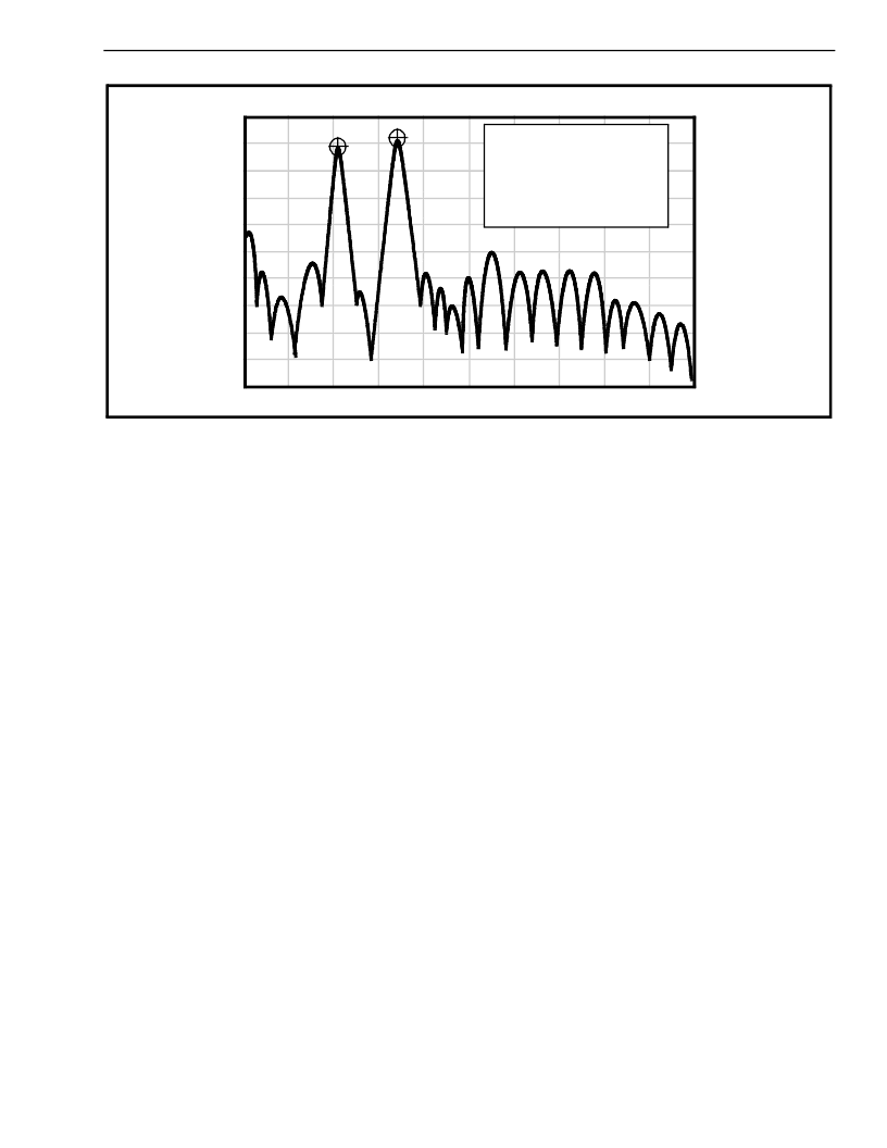
Figure 10 - Spectrum Plot
Scaling Information
10 dB/Div
Start Frequency = 0 Hz
Stop Frequency = 3400 Hz
Marker Frequency = 697 Hz and
1209 Hz
The period of each tone consists of 32 equal time
segments. The period of a tone is controlled by
varying the length of these time segments. During
write operations to the Transmit Data Register the 4
bit data on the bus is latched and converted to 2 of 8
coding for use by the programmable divider circuitry.
This code is used to specify a time segment length,
which will ultimately determine the frequency of the
tone. When the divider reaches the appropriate
count, as determined by the input code, a reset pulse
is issued and the counter starts again. The number
of time segments is fixed at 32, however, by varying
the segment length as described above the
frequency can also be varied. The divider output
clocks another counter, which addresses the
sinewave lookup ROM.
The lookup table contains codes which are used by
the switched capacitor D/A converter to obtain
discrete and highly accurate DC voltage levels. Two
identical circuits are employed to produce row and
column tones, which are then mixed using a low
noise summing amplifier. The oscillator described
needs no “start-up” time as in other DTMF
generators since the crystal oscillator is running
continuously thus providing a high degree of tone
burst accuracy. A bandwidth limiting filter is
incorporated and serves to attenuate distortion
products above 8 kHz. It can be seen from Figure 6
that the distortion products are very low in amplitude.
Burst Mode
In certain telephony applications it is required that
DTMF signals being generated are of a specific
duration
determined
either by
the particular
application or by any one of the exchange transmitter
specifications currently existing. Standard DTMF
signal timing can be accomplished by making use of
the Burst Mode. The transmitter is capable of issuing
symmetric bursts/pauses of predetermined duration.
This burst/pause duration is 51 ms±1 ms which is a
standard interval for autodialer and central office
applications. After the burst/pause has been issued,
the appropriate bit is set in the Status Register
indicating that the transmitter is ready for more data.
The timing described above is available when DTMF
mode has been selected. However, when CP mode
(Call Progress mode) is selected, the burst/pause
duration is doubled to 102 ms ±2 ms. Note that when
CP mode and Burst mode have been selected,
DTMF tones may be transmitted only and not
received. In applications where a non-standard
burst/pause time is desirable, a software timing loop
or external timer can be used to provide the timing
pulses when the burst mode is disabled by enabling
and disabling the transmitter.
Single Tone Generation
A single tone mode is available whereby individual
tones from the low group or high group can be
generated. This mode can be used for DTMF test
equipment
applications,
generation and distortion measurements. Refer to
Control Register B description for details.
acknowledgment
tone
相關(guān)PDF資料 |
PDF描述 |
|---|---|
| MT88L89AN | 3V Integrated DTMFTransceiver with Adaptive Micro Interface |
| MT88L89AP | 3V Integrated DTMFTransceiver with Adaptive Micro Interface |
| MT88L89AS | 3V Integrated DTMFTransceiver with Adaptive Micro Interface |
| MT88V32 | 8 x 4 High Performance Video Switch Array |
| MT88V32AP | 8 x 4 High Performance Video Switch Array |
相關(guān)代理商/技術(shù)參數(shù) |
參數(shù)描述 |
|---|---|
| MT88L89AN | 制造商:Microsemi Corporation 功能描述: |
| MT88L89AN1 | 制造商:Microsemi Corporation 功能描述:DTMF TXRX 3.58MHZ CMOS 3V 24SSOP - Rail/Tube |
| MT88L89ANR1 | 制造商:Microsemi Corporation 功能描述:DTMF TXRX 3.58MHZ CMOS 3V 24SSOP - Tape and Reel 制造商:MICROSEMI CONSUMER MEDICAL PRODUCT GROUP 功能描述:IC TXRX DTMF 3V 24SSOP 制造商:Microsemi Corporation 功能描述:IC TXRX DTMF 3V 24SSOP |
| MT88L89AP | 制造商:MITEL 制造商全稱:Mitel Networks Corporation 功能描述:3V Integrated DTMFTransceiver with Adaptive Micro Interface |
| MT88L89AS | 制造商:Microsemi Corporation 功能描述: |
發(fā)布緊急采購,3分鐘左右您將得到回復(fù)。