- 您現(xiàn)在的位置:買賣IC網(wǎng) > PDF目錄383642 > MT8888CE (Mitel Networks Corporation) Integrated DTMFTransceiver with Intel Micro Interface PDF資料下載
參數(shù)資料
| 型號: | MT8888CE |
| 廠商: | Mitel Networks Corporation |
| 英文描述: | Integrated DTMFTransceiver with Intel Micro Interface |
| 中文描述: | 綜合DTMFTransceiver與英特爾微型接口 |
| 文件頁數(shù): | 4/16頁 |
| 文件大小: | 302K |
| 代理商: | MT8888CE |
MT8888C/MT8888C-1
4-94
Following the filter section is a decoder employing
digital counting techniques to determine the
frequencies of the incoming tones and to verify that
they correspond to standard DTMF frequencies. A
complex averaging algorithm protects against tone
simulation by extraneous signals such as voice while
providing tolerance to small frequency deviations
and variations. This averaging algorithm has been
developed to ensure an optimum combination of
immunity to talk-off and tolerance to the presence of
interfering frequencies (third tones) and noise. When
the detector recognizes the presence of two valid
tones (this is referred to as the “signal condition” in
some industry specifications) the “Early Steering”
(ESt) output will go to an active state. Any
subsequent loss of signal condition will cause ESt to
assume an inactive state.
Steering Circuit
Before registration of a decoded tone pair, the
receiver checks for a valid signal duration (referred
to as character recognition condition). This check is
performed by an external RC time constant driven by
ESt. A logic high on ESt causes v
c
(see Figure 5) to
rise as the capacitor discharges. Provided that the
signal condition is maintained (ESt remains high) for
the validation period (t
GTP
), v
c
reaches the threshold
(V
TSt
) of the steering logic to register the tone pair,
latching its corresponding 4-bit code (see Table 1)
into the Receive Data Register. At this point the GT
output is activated and drives v
c
to V
DD
. GT
continues to drive high as long as ESt remains high.
Finally, after a short delay to allow the output latch to
settle, the delayed steering output flag goes high,
signalling that a received tone pair has been
registered. The status of the delayed steering flag
can be monitored by checking the appropriate bit in
the status register. If Interrupt mode has been
selected, the IRQ/CP pin will pull low when the
delayed steering flag is active.
The contents of the output latch are updated on an
active delayed steering transition. This data is
presented to the four bit bidirectional data bus when
the Receive Data Register is read. The steering
circuit works in reverse to validate the interdigit
pause between signals. Thus, as well as rejecting
signals too short to be considered valid, the receiver
will tolerate signal interruptions (drop out) too short
to be considered a valid pause. This facility, together
with the capability of selecting the steering time
constants externally, allows the designer to tailor
performance to meet a wide variety of system
requirements.
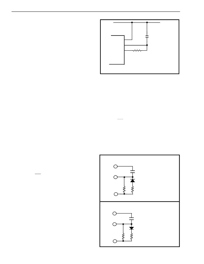
Figure 5 - Basic Steering Circuit
Guard Time Adjustment
The simple steering circuit shown in Figure 5 is
adequate for most applications. Component values
are chosen according to the following inequalities
(see Figure 7):
t
REC
≥
t
DPmax
+t
GTPmax
- t
DAmin
t
REC
≤
t
DPmin
+t
GTPmin
- t
DAmax
t
ID
≥
t
DAmax
+t
GTAmax
- t
DPmin
t
DO
≤
t
DAmin
+t
GTAmin
- t
DPmax
The value of t
DP
is a device parameter (see AC
Electrical Characteristics) and t
REC
is the minimum
signal duration to be recognized by the receiver. A
value for C1 of 0.1 μF is recommended for most
Figure 6 - Guard Time Adjustment
V
DD
V
DD
St/GT
ESt
C1
Vc
R1
MT8888C/
MT8888C-1
t
GTA
= (R1C1) In (V
DD
/ V
TSt
)
t
GTP
= (R1C1) In [V
DD
/ (V
DD
-V
TSt
)]
V
DD
St/GT
ESt
V
DD
St/GT
ESt
C1
R1
R2
C1
R1
R2
t
GTA
= (R1C1) In (V
DD
/V
TSt
)
R
P
= (R1R2) / (R1 + R2)
t
GTP
= (R
P
C1) In [V
DD
/ (V
DD
-V
TSt
)]
t
GTA
= (R
p
C1) In (V
DD
/V
TSt
)
R
P
= (R1R2) / (R1 + R2)
t
GTP
= (R1C1) In [V
DD
/ (V
DD
-V
TSt
)]
a) decreasing tGTP; (tGTP < tGTA)
b) decreasing tGTA; (tGTP > tGTA)
相關(guān)PDF資料 |
PDF描述 |
|---|---|
| MT8888CN | Integrated DTMFTransceiver with Intel Micro Interface |
| MT8888CS | Integrated DTMFTransceiver with Intel Micro Interface |
| MT8888CC-1 | Integrated DTMFTransceiver with Intel Micro Interface |
| MT88E39 | CMOS Calling Number Identification Circuit(CNIC1.1) |
| MT88E39AS | XLR Style Audio Connector |
相關(guān)代理商/技術(shù)參數(shù) |
參數(shù)描述 |
|---|---|
| MT8888CE1 | 制造商:Microsemi Corporation 功能描述:DTMF TXRX 3.58MHZ CMOS 5V 20PDIP - Rail/Tube 制造商:Microsemi Corporation 功能描述:PB FREE DTMF TRANSCEIVER 制造商:MICROSEMI CONSUMER MEDICAL PRODUCT GROUP 功能描述:IC TXRX DTMF 20PDIP 制造商:Microsemi Corporation 功能描述:IC TXRX DTMF 20PDIP |
| MT8888CE-1 | 制造商:MITEL 制造商全稱:Mitel Networks Corporation 功能描述:Integrated DTMFTransceiver with Intel Micro Interface |
| MT8888CN | 制造商:Microsemi Corporation 功能描述: |
| MT8888CN1 | 制造商:Microsemi Corporation 功能描述: 制造商:Microsemi Corporation 功能描述:DTMF TXRX 3.58MHZ CMOS 5V 24SSOP - Rail/Tube 制造商:MICROSEMI CONSUMER MEDICAL PRODUCT GROUP 功能描述:IC TXRX DTMF 24SSOP 制造商:Microsemi Corporation 功能描述:IC TXRX DTMF 24SSOP |
| MT8888CN-1 | 制造商:MITEL 制造商全稱:Mitel Networks Corporation 功能描述:Integrated DTMFTransceiver with Intel Micro Interface |
發(fā)布緊急采購,3分鐘左右您將得到回復(fù)。