- 您現(xiàn)在的位置:買賣IC網(wǎng) > PDF目錄383640 > MT3371B (Mitel Networks Corporation) Wide Dynamic Range DTMF Receiver(50dB的寬動(dòng)態(tài)范圍雙音多頻信號(hào)(DTMF)接收器) PDF資料下載
參數(shù)資料
| 型號(hào): | MT3371B |
| 廠商: | Mitel Networks Corporation |
| 英文描述: | Wide Dynamic Range DTMF Receiver(50dB的寬動(dòng)態(tài)范圍雙音多頻信號(hào)(DTMF)接收器) |
| 中文描述: | 寬動(dòng)態(tài)范圍的DTMF接收器(50分貝的寬動(dòng)態(tài)范圍雙音多頻信號(hào)(DTMF)的接收器) |
| 文件頁(yè)數(shù): | 5/11頁(yè) |
| 文件大小: | 70K |
| 代理商: | MT3371B |
MT3170B/71B, MT3270B/71B, MT3370B/71B
4-7
Table 4. Recommended Resonator and Crystal
Specifications
Note:
Qm=quality factor of RLC model, i.e., 1/2
Π
R1C1.
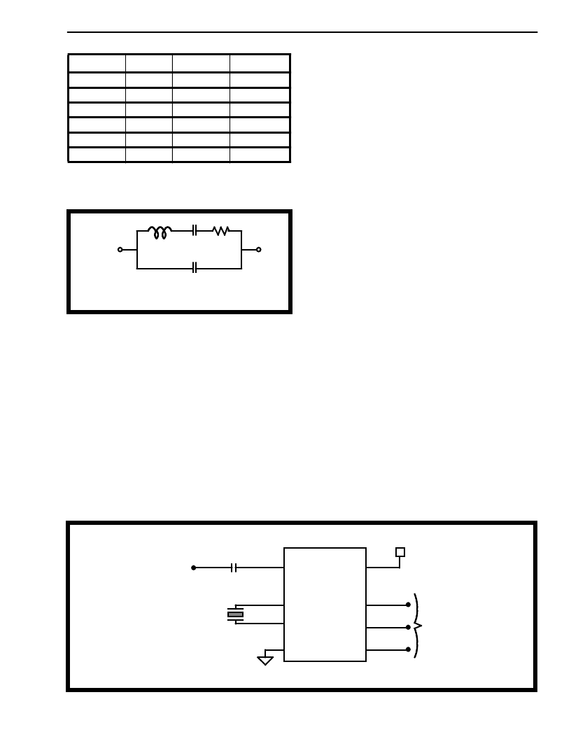
Resonator and Crystal Electric Equivalent Circuit
Oscillator
The MT327xB/337xB can be used in both external
clock or two pin oscillator mode. In two pin oscillator
mode, the oscillator circuit is completed by
connecting either a 4.194304 MHz crystal or ceramic
resonator
across
OSC1
Specifications of the ceramic resonator and crystal
are tabulated in Table 4. It is also possible to
configure a number of these devices employing only
a single oscillator crystal. The OSC2 output of the
first device in the chain is connected to the OSC1
input of the next device. Subsequent devices are
connected similarily. The oscillator circuit can also
and
OSC2
pins.
be driven by an 4.194304 MHz external clock applied
on pin OSC 1. The OSC2 pin should be left open.
For MT317xB devices , the CLK input is driven
directly by an 4.194304 MHz external digital clock.
Applications
The circuit shown in Figure 3 illustrates the use of a
MT327xB in a typical receiver application. It requires
only a coupling capacitor (C1) and a crystal or
ceramic resonator (X1) to complete the circuit.
The MT3x70B is designed for user who wishes to
tailor the guard time for specific applications. When
a DTMF signal is present, the ESt pin will go high.
An external microcontroller monitors ESt in real time
for a period of time set by the user. A guard time
algorithm must be implemented such that DTMF
signals not meeting the timing requirements are
rejected. The MT3x71B uses an internal counter to
provide a preset DTMF validation period. It requires
no external components. The DStD output high
indicates that a valid DTMF digit has been detected.
The 4.194304 MHz frequency has a secondary
advantage in some applications where a real time
clock is required. A 22-bit counter will count
4,194,304 cycles to provide a one second time base.
Parameter
Unit
Resonator
Crystal
R1
L1
C1
C0
Qm
f
Ohms
mH
pF
pF
-
%
6.580
0.359
4.441
34.890
1.299E+03
±
0.2%
150
95.355
15.1E-03
12.0
101.2E+ 03
±
0.01%
R1 = Equivalent resistor.
L1 = Equivalent inductance.
C1 = Equivalent compliance.
C0 = Capacitance between electrode.
L1
C1
R1
C0
Figure 3 - Application Circuit for MT327xB
DTMF/CP Input
C1
X1
1
2
3
4
8
7
6
5
INPUT
OSC2
OSC1
V
SS
V
DD
ESt/DStD
ACK
SD
V
DD
COMPONENTS LIST:
C
1
= 0.1
μ
F
±
10 %
X1 = Crystal or Resonator (4.194304 MHz)
To microprocessor or
microcontroller
MT327xB
相關(guān)PDF資料 |
PDF描述 |
|---|---|
| MT34013 | EIGHT CHANNEL ARINC DECODER |
| MT62901D9A | ARINC629 ENCODER/DECODER |
| MT62901 | ARINC629 ENCODER/DECODER |
| MT62901D2 | ARINC629 ENCODER/DECODER |
| MT62901D2A | ARINC629 ENCODER/DECODER |
相關(guān)代理商/技術(shù)參數(shù) |
參數(shù)描述 |
|---|---|
| MT3371BN | 制造商:Microsemi Corporation 功能描述: |
| MT3371BN1 | 制造商:Microsemi Corporation 功能描述:DTMF RX 4.19MHZ 5V 20SSOP - Rail/Tube |
| MT3371BNR | 制造商:ZARLINK 制造商全稱:Zarlink Semiconductor Inc 功能描述:Wide Dynamic Range DTMF Receiver |
| MT3371BNR1 | 制造商:Microsemi Corporation 功能描述:DTMF RX 4.19MHZ 5V 20SSOP - Tape and Reel 制造商:Zarlink Semiconductor Inc 功能描述:DTMF RX 4.19MHZ 5V 20SSOP - Tape and Reel |
| MT3371BS | 制造商:Microsemi Corporation 功能描述:DTMF RX 4.19MHZ 5V 18SOIC - Bulk |
發(fā)布緊急采購(gòu),3分鐘左右您將得到回復(fù)。