- 您現(xiàn)在的位置:買賣IC網(wǎng) > PDF目錄299509 > MQHL-28-05D-W-ES (SYNQOR INC) 2-OUTPUT 50 W DC-DC REG PWR SUPPLY MODULE PDF資料下載
參數(shù)資料
| 型號: | MQHL-28-05D-W-ES |
| 廠商: | SYNQOR INC |
| 元件分類: | 電源模塊 |
| 英文描述: | 2-OUTPUT 50 W DC-DC REG PWR SUPPLY MODULE |
| 封裝: | MODULE-12 |
| 文件頁數(shù): | 10/14頁 |
| 文件大小: | 3516K |
| 代理商: | MQHL-28-05D-W-ES |
Product # MQHL-28-05D
Phone 1-888-567-9596
www.synqor.com
Doc.# 005-0005592 Rev. 2
05/03/10
Page 5
Output:
Current:
±5.0V
10A Total
MQHL-28-05D
Technical Specification
BASIC OPERATION AND FEATURES
The MQHL DC/DC converter uses a two-stage power
conversion topology. The first, or regulation, stage is a
buck-converter that keeps the output voltage constant over
variations in line, load, and temperature. The second, or
isolation, stage uses transformers to provide the functions of
input/output isolation and voltage transformation to achieve
the output voltage required.
In the dual output converter there are two secondary
windings in the transformer of the isolation stage, one for
each output. There is only one regulation stage, however,
and it is used to control the positive output. The negative
output therefore displays “Cross-Regulation”, meaning that
its output voltage depends on how much current is drawn
from each output.
Both the positive and the negative outputs share a common
OUTPUT RETURN pin.
Both the regulation and the isolation stages switch at a fixed
frequency for predictable EMI performance. The isolation
stage switches at one half the frequency of the regulation
stage, but due to the push-pull nature of this stage it creates
a ripple at double its switching frequency. As a result, both
the input and the output of the converter have a fundamental
ripple frequency of about 550 kHz in the free-running mode.
Rectification of the isolation stage’s output is accomplished
with synchronous rectifiers.
These devices, which are
MOSFETs with a very low resistance, dissipate far less energy
than would Schottky diodes. This is the primary reason why
the MQHL converters have such high efficiency, particularly
at low output voltages.
Besides improving efficiency, the synchronous rectifiers
permit operation down to zero load current. There is no
longer a need for a minimum load, as is typical for converters
that use diodes for rectification. The synchronous rectifiers
actually permit a negative load current to flow back into the
converter’s output terminals if the load is a source of short
or long term energy. The MQHL converters employ a “back-
drive current limit” to keep this negative output terminal
current small.
There is a control circuit in the MQHL converter that
determines the conduction state of the power switches.
It communicates across the isolation barrier through a
magnetically coupled device. No opto-isolators are used.
An input under-voltage shutdown feature with hysteresis is
provided, as well as an input over-voltage shutdown and an
output over-voltage limit. There is also an output current
limit that is nearly constant as the load impedance decreases
(i.e., there is not fold-back or fold-forward characteristic to
the output current under this condition). When a load fault
is removed, the output voltage rises exponentially to its
nominal value without an overshoot. If a load fault pulls the
output voltage below about 60% of nominal, the converter
will shut down to attempt to clear the load fault. After a
short delay it will try to auto-restart.
The MQHL converter’s control circuit does not implement an
over-temperature shutdown.
The following sections describe the use and operation of
additional control features provided by the MQHL converter.
CONTROL FEATURES
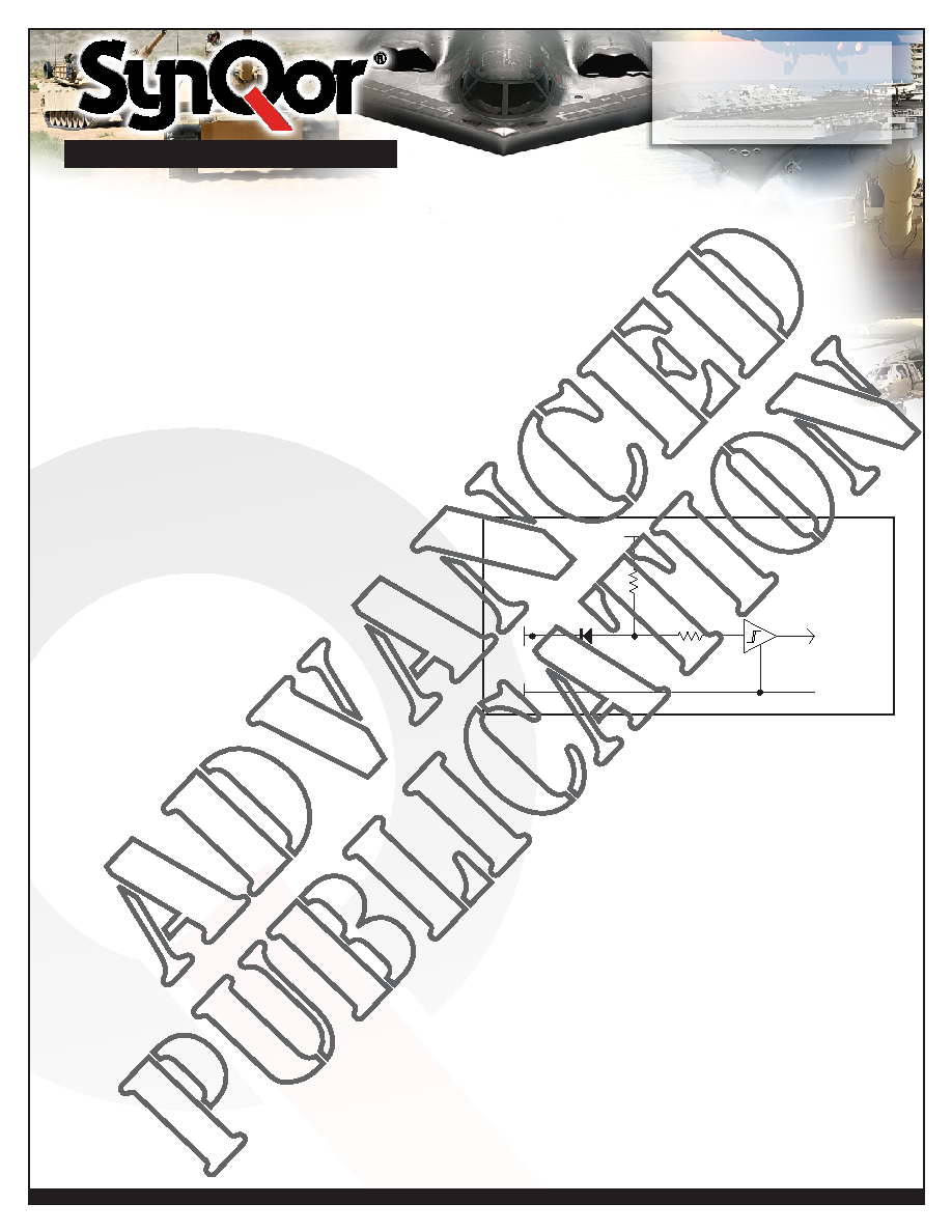
ENABLE: The MQHL converter has one enable pin, ENA1
(pin 4), which is referenced with respect to the converter’s
input return (pin 2). It must have a logic high level for the
converter to be enabled; a logic low inhibits the converter.
The enable pin is internally pulled high so that an open
connection will enable the converter. Figure A shows the
equivalent circuit looking into the enable pin. It is TTL
compatible and has hysteresis.
SHUTDOWN: The MQHL converter will shut down in
response to only five conditions: ENA input low, VIN input
below under-voltage shutdown threshold, VIN input above
over-voltage shutdown threshold, output voltage below the
output under-voltage threshold, and output voltage above
the output over-voltage threshold. Following any shutdown
event, there is a startup inhibit delay which will prevent the
converter from restarting for approximately 100ms. After
the 100ms delay elapses, if the enable inputs are high and
the input voltage is within the operating range, the converter
will restart. If the VIN input is brought down to nearly 0V
and back into the operating range, there is no startup inhibit,
and the output voltage will rise according to the “Turn-On
Delay, Rising Vin” specification.
SYNCHRONIZATION: The MQHL converter’s switching
frequency can be synchronized to an external frequency
source that is in the 500 kHz to 700 kHz range. A pulse
train at the desired frequency should be applied to the SYNC
IN pin (pin 6) with respect to the INPUT RETURN (pin 2).
This pulse train should have a duty cycle in the 20% to 80%
range. Its low value should be below 0.8V to be guaranteed
to be interpreted as a logic low, and its high value should
ENA1
5V
82.5K
10K
TO ENABLE
CIRCUITRY
PIN4
PIN2
IN RTN
Figure A: Equivalent circuit looking into the ENA1 pin.
be above 2.0V to be guaranteed to be interpreted as a logic
high. The transition time between the two states should be
less than 300ns.
If the MQHL converter is not to be synchronized, the SYNC
IN pin should be left open circuit.
The converter will
then operate in its free-running mode at a frequency of
approximately 550 kHz.
If, due to a fault, the SYNC IN pin is held in either a logic low
or logic high state continuously, or the SYNC IN frequency
is outside the 500-700 kHz range, the MQHL converter will
revert to its free-running frequency.
The MQHL converter also has a SYNC OUT pin (pin 5). This
output can be used to drive the SYNC IN pins of as many as
ten (10) other MQHL converters. The pulse train coming out
of SYNC OUT has a duty cycle of 50% and a frequency that
matches the switching frequency of the converter with which
it is associated. This frequency is either the free-running
frequency if there is no valid synchronization signal at the
SYNC IN pin, or the synchronization frequency if there is.
The synchronization feature is entirely compatible with that
of SynQor’s MQFL family of converters.
Figure B shows the equivalent circuit looking into the SYNC
IN pin and Figure C shows the equivalent circuit looking into
the SYNC OUT pin.
OUTPUT VOLTAGE TRIM: If desired, it is possible to
increase or decrease the MQHL dual converter’s output
voltage from its nominal value. To increase the output
voltage a resistor, Rup, should be connected between TRIM
pin (pin 10) and the OUTPUT RETURN pin (pin 8), as shown
in Figure E. The value of this resistor should be determined
according to the following equation of from Figure D:
where:
Vnom = the converter’s nominal output voltage,
Vout = the desired output voltage (greater than
Vnom), and
Rtrim up is in Ohms.
To decrease the output voltage a resistor, Rdown, should be
connected between the TRIM pin and the POSITIVE OUTPUT
pin (pin 7), as shown in Figure E. The value of this resistor
should be determined according to the following equation:
where:
Vnom = the converter’s nominal output voltage,
Vout = the desired output voltage (less than Vnom),
and
Rtrim down is in Ohms.
As the output voltage is trimmed up, it produces a greater
voltage stress on the converter’s internal components and
may cause the converter to fail to deliver the desired output
voltage at the low end of the input voltage range at the
higher end of the load current and temperature range.
Please consult the factory for details. Factory trimmed
converters are available by request.
PIN 2
PIN 6
5K
5V
SYNC IN
IN RTN
TO SYNC
CIRCUITRY
5K
Figure B: Equivalent circuit looking into the SYNC IN pin with
respect to the IN RTN (input return) pin.
FROM SYNC
CIRCUITRY
5K
5V
SYNC OUT
IN RTN
PIN 2
PIN 5
OPEN COLLECTOR
OUTPUT
Figure C: Equivalent circuit looking into SYNC OUT pin with
respect to the IN RTN (input return) pin.
Figure D: Trim up and Trim down as a function of external trim resistance.
advanced
publication
advanced
publication
advanced
publication
advanced
publication
相關(guān)PDF資料 |
PDF描述 |
|---|---|
| MQHL-28-2R5S-X-ES | 1-OUTPUT 50 W DC-DC REG PWR SUPPLY MODULE |
| MQHL-28E-15D-Z-C | 2-OUTPUT 50 W DC-DC REG PWR SUPPLY MODULE |
| MR27V25603L-XXXTME | 16M X 16 MASK PROM, 120 ns, PDSO50 |
| MR4027P | UNIDIRECTIONAL, SILICON, TVS DIODE |
| MR7580-100P1BP | 100 CONTACT(S), MALE, D MICROMINIATURE CONNECTOR, SOLDER |
相關(guān)代理商/技術(shù)參數(shù) |
參數(shù)描述 |
|---|---|
| MQHL-28-05S | 制造商:SYNQOR 制造商全稱:SYNQOR 功能描述:HIGH RELIABILITY DC-DC CONVERTER |
| MQHL-28-05S-W-ES | 制造商:SynQor 功能描述:CONVERTER |
| MQHL-28-05S-Y-ES | 制造商:SYNQOR 制造商全稱:SYNQOR 功能描述:HIGH RELIABILITY DC-DC CONVERTER |
| MQHL-28-12S | 制造商:SYNQOR 制造商全稱:SYNQOR 功能描述:HIGH RELIABILITY DC-DC CONVERTER |
| MQHL-28-12S-Y-ES | 制造商:SYNQOR 制造商全稱:SYNQOR 功能描述:HIGH RELIABILITY DC-DC CONVERTER |
發(fā)布緊急采購,3分鐘左右您將得到回復(fù)。