- 您現(xiàn)在的位置:買賣IC網(wǎng) > PDF目錄45374 > MPC92439EI (INTEGRATED DEVICE TECHNOLOGY INC) 900 MHz, OTHER CLOCK GENERATOR, PQCC28 PDF資料下載
第1頁(yè)第2頁(yè)第3頁(yè)第4頁(yè)第5頁(yè)第6頁(yè)第7頁(yè)第8頁(yè)第9頁(yè)第10頁(yè)第11頁(yè)當(dāng)前第12頁(yè)第13頁(yè)第14頁(yè)第15頁(yè)

MPC92439 Data Sheet
900MHZ, LOW VOLTAGE, LVPECL CLOCK SYNTHESIZER
MPC92439 REVISION 4 OCTOBER 27, 2009
6
2009 Integrated Device Technology, Inc.
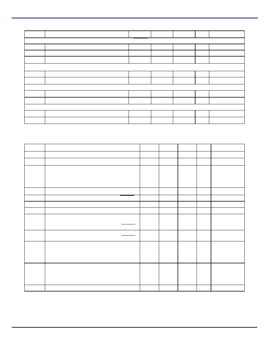
Table 6. DC Characteristics (VCC = 3.3V ± 5%, TA = 0°C to +70°C)
Symbol
Characteristics
Min
Typ
Max
Unit
Condition
LVCMOS Control Inputs (FREF_EXT, POWER_DOWN, XTAL_SEL, P_LOAD, S_LOAD, S_DATA, S_CLOCK, M[0:8], N[0:1]. OE)
VIH
Input High Voltage
2.0
VCC + 0.3
V
LVCMOS
VIL
Input Low Voltage
0.8
V
LVCMOS
IIN
Input Current(1)
1. Inputs have pull-down resistors affecting the input current.
±200
AVIN = VCC or GND
Differential Clock Output FOUT(2)
2. Outputs terminated 50
to VTT = VCC – 2V.
VOH
Output High Voltage
VCC–1.02
VCC–0.74
V
LVPECL
VOL
Output Low Voltage
VCC–1.95
VCC–1.60
V
LVPECL
Test and Diagnosis Output TEST
VOH
Output High Voltage
2.0
V
IOH = –0.8 mA
VOL
Output Low Voltage
0.55
V
IOL = 0.8 mA
Supply Current
ICC_PLL
Maximum PLL Supply Current
20
mA
VCC_PLL Pins
ICC
Maximum Supply Current
62
110
mA
All VCC Pins
Table 7. AC Characteristics (VCC = 3.3 V ± 5%, TA = 0°C to +70°C)(1)
1. AC characteristics apply for parallel output termination of 50
to VTT.
Symbol
Characteristics
Min
Typ
Max
Unit
Condition
fXTAL
Crystal interface frequency range
10
20
MHz
fVCO
VCO frequency range(2)
2. The input frequency fXTAL and the PLL feedback divider M must match the VCO frequency range: fVCO = fXTAL M
400
900
MHz
fMAX
Output Frequency
N = 11 (
÷1)
N = 00 (
÷2)
N = 01 (
÷4)
N = 10 (
÷8)
400
200
100
50
900
450
225
112.5
MHz
PWR_DOWN = 0
fS_CLOCK
Serial Interface Programming Clock Frequency(3)
3. The frequency of S_CLOCK is limited to 10 MHz in serial programming mode. S_CLOCK can be switched at higher frequencies when used
as test clock in test mode 6. See APPLICATIONS INFORMATION for more details.
010
MHz
tP,MIN
Minimum Pulse Width
(S-LOAD, P_LOAD)50
ns
DC
Output Duty Cycle
45
50
55
%
tr, tf
Output Rise/Fall Time
0.05
0.3
ns
20% to 80%
tS
Setup Time
S_DATA to S_CLOCK
S_CLOCK to S_LOAD
M, N to P_LOAD
20
ns
tS
Hold Time
S_DATA to S_CLOCK
M, N to P_LOAD
20
ns
tJIT(CC)
Cycle-to-cycle jitter (RMS 1
σ)(4)
N=11 (÷1)
N=00 (÷2)
N=01 (÷4)
N=10 (÷8)
4. Maximum cycle jitter measured at the lowest VCO frequency. Figure 5 shows the cycle jitter vs. frequency characteristics
12
25
55
65
ps
tJIT(CC)
Period jitter (RMS 1
σ)(5)
N=11 (÷1)
N=00 (÷2)
N=01 (÷4)
N=10 (÷8)
5. Maximum period jitter measured at the lowest VCO frequency. Figure 6 shows the period jitter vs. frequency characteristics
13
23
36
40
tLOCK
Maximum PLL Lock Time
10
ms
相關(guān)PDF資料 |
PDF描述 |
|---|---|
| MPC92439EI | 900 MHz, OTHER CLOCK GENERATOR, PQCC28 |
| MPC92439EIR2 | 900 MHz, OTHER CLOCK GENERATOR, PQCC28 |
| MPC92439FNR2 | 900 MHz, OTHER CLOCK GENERATOR, PQCC28 |
| MPC92439FN | 900 MHz, OTHER CLOCK GENERATOR, PQCC28 |
| MPC92439FAR2 | 900 MHz, OTHER CLOCK GENERATOR, PQFP32 |
相關(guān)代理商/技術(shù)參數(shù) |
參數(shù)描述 |
|---|---|
| MPC92439EIR2 | 功能描述:時(shí)鐘合成器/抖動(dòng)清除器 FSL 900MHz LVPECL Freq. Synthesizer RoHS:否 制造商:Skyworks Solutions, Inc. 輸出端數(shù)量: 輸出電平: 最大輸出頻率: 輸入電平: 最大輸入頻率:6.1 GHz 電源電壓-最大:3.3 V 電源電壓-最小:2.7 V 封裝 / 箱體:TSSOP-28 封裝:Reel |
| MPC92439FA | 制造商:IDT 制造商全稱:Integrated Device Technology 功能描述:900MHz, Low Voltage, LVPECL Clock Syntheesizer |
| MPC92439KLF | 制造商:IDT 制造商全稱:Integrated Device Technology 功能描述:900MHz, Low Voltage, LVPECL Clock Syntheesizer |
| MPC92469 | 制造商:IDT 制造商全稱:Integrated Device Technology 功能描述:400 MHz Low Voltage PECL Clock Synthesizer w/Spread Spectrum |
| MPC92469AC | 功能描述:時(shí)鐘合成器/抖動(dòng)清除器 LVPECL Clock Synthesizer RoHS:否 制造商:Skyworks Solutions, Inc. 輸出端數(shù)量: 輸出電平: 最大輸出頻率: 輸入電平: 最大輸入頻率:6.1 GHz 電源電壓-最大:3.3 V 電源電壓-最小:2.7 V 封裝 / 箱體:TSSOP-28 封裝:Reel |
發(fā)布緊急采購(gòu),3分鐘左右您將得到回復(fù)。