- 您現(xiàn)在的位置:買賣IC網(wǎng) > PDF目錄371134 > MPC755BPX300LE (MOTOROLA INC) RISC Microprocessor Hardware Specifications PDF資料下載
參數(shù)資料
| 型號: | MPC755BPX300LE |
| 廠商: | MOTOROLA INC |
| 元件分類: | 微控制器/微處理器 |
| 英文描述: | RISC Microprocessor Hardware Specifications |
| 中文描述: | 32-BIT, 300 MHz, RISC PROCESSOR, PBGA360 |
| 封裝: | 25 X 25 MM, PLASTIC, BGA-360 |
| 文件頁數(shù): | 11/56頁 |
| 文件大?。?/td> | 1652K |
| 代理商: | MPC755BPX300LE |
第1頁第2頁第3頁第4頁第5頁第6頁第7頁第8頁第9頁第10頁當(dāng)前第11頁第12頁第13頁第14頁第15頁第16頁第17頁第18頁第19頁第20頁第21頁第22頁第23頁第24頁第25頁第26頁第27頁第28頁第29頁第30頁第31頁第32頁第33頁第34頁第35頁第36頁第37頁第38頁第39頁第40頁第41頁第42頁第43頁第44頁第45頁第46頁第47頁第48頁第49頁第50頁第51頁第52頁第53頁第54頁第55頁第56頁
MPC755 RISC Microprocessor Hardware Specifications, Rev. 6.1
Freescale Semiconductor
11
Electrical and Thermal Characteristics
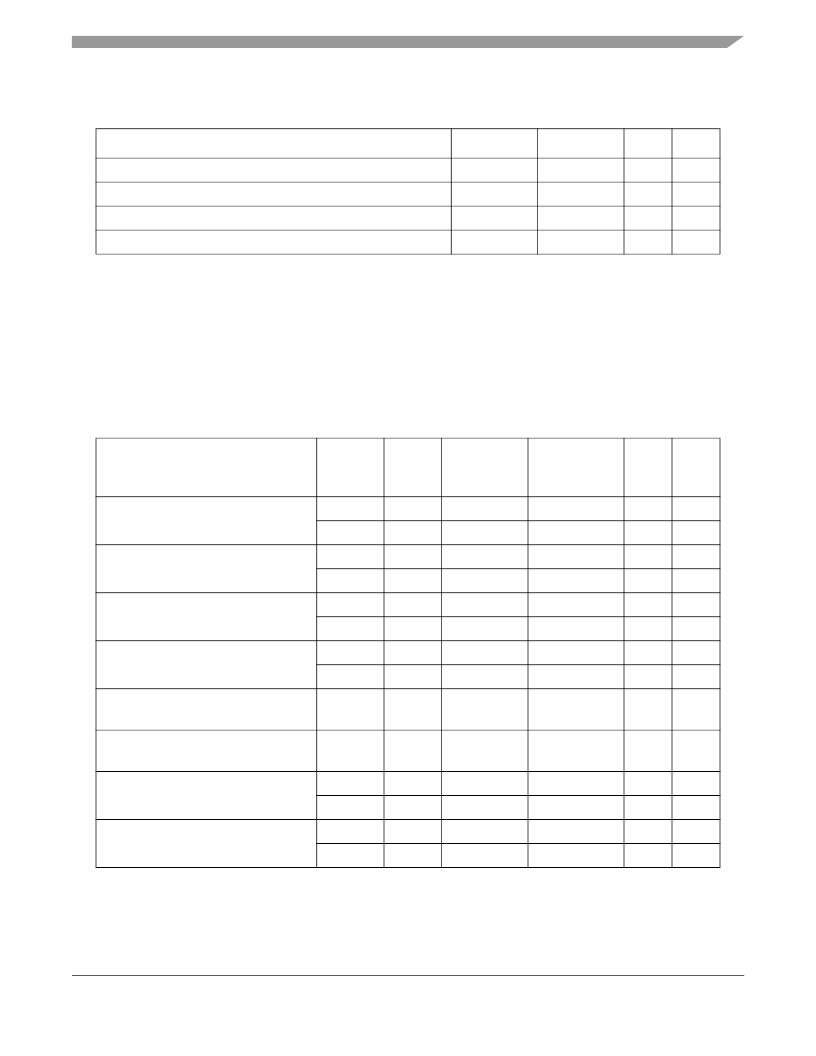
Table 6
provides the DC electrical characteristics for the MPC755.
Table 5. Thermal Sensor Specifications
At recommended operating conditions (see
Table 3
)
Characteristic
Min
Max
Unit
Notes
Temperature range
0
127
°C
1
Comparator settling time
20
—
μs
2, 3
Resolution
4
—
°C
3
Accuracy
–12
+12
°C
3
Notes:
1. The temperature is the junction temperature of the die. The thermal assist unit’s raw output does not indicate an absolute temperature, but
must be interpreted by software to derive the absolute junction temperature. For information about the use and calibration of the TAU, see
Freescale Application Note AN1800/D,
Programming the Thermal Assist Unit in the MPC750 Microprocessor.
2. The comparator settling time value must be converted into the number of CPU clocks that need to be written into the THRM3 SPR.
3. Guaranteed by design and characterization.
Table 6. DC Electrical Specifications
At recommended operating conditions (see
Table 3
)
Characteristic
Nominal
Bus Voltage
1
Symbol
Min
Max
Unit
Notes
Input high voltage (all inputs except SYSCLK)
2.5
V
IH
1.6
(L2)OV
DD
+ 0.3
V
2, 3
3.3
V
IH
2.0
(L2)OV
DD
+ 0.3
V
2, 3
Input low voltage (all inputs except SYSCLK)
2.5
V
IL
–0.3
0.6
V
2
3.3
V
IL
–0.3
0.8
V
SYSCLK input high voltage
2.5
KV
IH
1.8
OV
DD
+ 0.3
V
3.3
KV
IH
2.4
OV
DD
+ 0.3
V
SYSCLK input low voltage
2.5
KV
IL
–0.3
0.4
V
3.3
KV
IL
–0.3
0.4
V
Input leakage current,
V
in
= L2OV
DD
/OV
DD
I
in
—
10
μA
2, 3
High-Z (off-state) leakage current,
V
in
= L2OV
DD
/OV
DD
I
TSI
—
10
μA
2, 3, 5
Output high voltage, I
OH
=
–6
mA
2.5
V
OH
1.7
—
V
3.3
V
OH
2.4
—
V
Output low voltage, I
OL
=
6
mA
2.5
V
OL
—
0.45
V
3.3
V
OL
—
0.4
V
相關(guān)PDF資料 |
PDF描述 |
|---|---|
| MPC8240EC | Integrated Processor Hardware Specifications |
| MPC8240 | 32-Bit Microprocessor(32位微處理器) |
| MPC8260ACZU | MPC826xA (HiP4) Family Hardware Specifications |
| MPC8260CZU | MPC826xA (HiP4) Family Hardware Specifications |
| MPC8264ACZU | MPC826xA (HiP4) Family Hardware Specifications |
相關(guān)代理商/技術(shù)參數(shù) |
參數(shù)描述 |
|---|---|
| MPC755BPX350LE | 功能描述:微處理器 - MPU 360PBGA,RV2.8,HIP4DP RoHS:否 制造商:Atmel 處理器系列:SAMA5D31 核心:ARM Cortex A5 數(shù)據(jù)總線寬度:32 bit 最大時(shí)鐘頻率:536 MHz 程序存儲器大小:32 KB 數(shù)據(jù) RAM 大小:128 KB 接口類型:CAN, Ethernet, LIN, SPI,TWI, UART, USB 工作電源電壓:1.8 V to 3.3 V 最大工作溫度:+ 85 C 安裝風(fēng)格:SMD/SMT 封裝 / 箱體:FBGA-324 |
| MPC755BRX300LE | 功能描述:微處理器 - MPU 360CBGARV2.8HIP4DP RoHS:否 制造商:Atmel 處理器系列:SAMA5D31 核心:ARM Cortex A5 數(shù)據(jù)總線寬度:32 bit 最大時(shí)鐘頻率:536 MHz 程序存儲器大小:32 KB 數(shù)據(jù) RAM 大小:128 KB 接口類型:CAN, Ethernet, LIN, SPI,TWI, UART, USB 工作電源電壓:1.8 V to 3.3 V 最大工作溫度:+ 85 C 安裝風(fēng)格:SMD/SMT 封裝 / 箱體:FBGA-324 |
| MPC755BRX350LE | 功能描述:微處理器 - MPU 360CBGA,RV2.8,HIP4DP RoHS:否 制造商:Atmel 處理器系列:SAMA5D31 核心:ARM Cortex A5 數(shù)據(jù)總線寬度:32 bit 最大時(shí)鐘頻率:536 MHz 程序存儲器大小:32 KB 數(shù)據(jù) RAM 大小:128 KB 接口類型:CAN, Ethernet, LIN, SPI,TWI, UART, USB 工作電源電壓:1.8 V to 3.3 V 最大工作溫度:+ 85 C 安裝風(fēng)格:SMD/SMT 封裝 / 箱體:FBGA-324 |
| MPC755BRX350TE | 功能描述:微處理器 - MPU 360CBGA,RV2.8,HIP4DP RoHS:否 制造商:Atmel 處理器系列:SAMA5D31 核心:ARM Cortex A5 數(shù)據(jù)總線寬度:32 bit 最大時(shí)鐘頻率:536 MHz 程序存儲器大小:32 KB 數(shù)據(jù) RAM 大小:128 KB 接口類型:CAN, Ethernet, LIN, SPI,TWI, UART, USB 工作電源電壓:1.8 V to 3.3 V 最大工作溫度:+ 85 C 安裝風(fēng)格:SMD/SMT 封裝 / 箱體:FBGA-324 |
| MPC755BVT300LE | 功能描述:微處理器 - MPU RV2.8106C RoHS:否 制造商:Atmel 處理器系列:SAMA5D31 核心:ARM Cortex A5 數(shù)據(jù)總線寬度:32 bit 最大時(shí)鐘頻率:536 MHz 程序存儲器大小:32 KB 數(shù)據(jù) RAM 大小:128 KB 接口類型:CAN, Ethernet, LIN, SPI,TWI, UART, USB 工作電源電壓:1.8 V to 3.3 V 最大工作溫度:+ 85 C 安裝風(fēng)格:SMD/SMT 封裝 / 箱體:FBGA-324 |
發(fā)布緊急采購,3分鐘左右您將得到回復(fù)。