- 您現(xiàn)在的位置:買賣IC網(wǎng) > PDF目錄45343 > MPC5646CF0CLU8 (FREESCALE SEMICONDUCTOR INC) 32-BIT, FLASH, 80 MHz, MICROCONTROLLER, PQFP176 PDF資料下載
參數(shù)資料
| 型號: | MPC5646CF0CLU8 |
| 廠商: | FREESCALE SEMICONDUCTOR INC |
| 元件分類: | 微控制器/微處理器 |
| 英文描述: | 32-BIT, FLASH, 80 MHz, MICROCONTROLLER, PQFP176 |
| 封裝: | 24 X 24 MM, 1.40 MM HEIGHT, 0.50 MM PITCH, ROHS COMPLIANT, LQFP-176 |
| 文件頁數(shù): | 48/115頁 |
| 文件大小: | 783K |
| 代理商: | MPC5646CF0CLU8 |
第1頁第2頁第3頁第4頁第5頁第6頁第7頁第8頁第9頁第10頁第11頁第12頁第13頁第14頁第15頁第16頁第17頁第18頁第19頁第20頁第21頁第22頁第23頁第24頁第25頁第26頁第27頁第28頁第29頁第30頁第31頁第32頁第33頁第34頁第35頁第36頁第37頁第38頁第39頁第40頁第41頁第42頁第43頁第44頁第45頁第46頁第47頁當前第48頁第49頁第50頁第51頁第52頁第53頁第54頁第55頁第56頁第57頁第58頁第59頁第60頁第61頁第62頁第63頁第64頁第65頁第66頁第67頁第68頁第69頁第70頁第71頁第72頁第73頁第74頁第75頁第76頁第77頁第78頁第79頁第80頁第81頁第82頁第83頁第84頁第85頁第86頁第87頁第88頁第89頁第90頁第91頁第92頁第93頁第94頁第95頁第96頁第97頁第98頁第99頁第100頁第101頁第102頁第103頁第104頁第105頁第106頁第107頁第108頁第109頁第110頁第111頁第112頁第113頁第114頁第115頁
MPC5646C Microcontroller Datasheet, Rev. 4
Preliminary—Subject to Change Without Notice
Electrical Characteristics
Freescale Semiconductor
38
4
Electrical Characteristics
This section contains electrical characteristics of the device as well as temperature and power considerations.
This product contains devices to protect the inputs against damage due to high static voltages. However, it is advisable to take
precautions to avoid application of any voltage higher than the specified maximum rated voltages.
To enhance reliability, unused inputs can be driven to an appropriate logic voltage level (VDD or VSS_HV). This could be done
by the internal pull-up and pull-down, which is provided by the product for most general purpose pins.
The parameters listed in the following tables represent the characteristics of the device and its demands on the system.
In the tables where the device logic provides signals with their respective timing characteristics, the symbol “CC” for Controller
Characteristics is included in the Symbol column.
In the tables where the external system must provide signals with their respective timing characteristics to the device, the symbol
“SR” for System Requirement is included in the Symbol column.
4.1
Parameter classification
The electrical parameters shown in this supplement are guaranteed by various methods. To give the customer a better
understanding, the classifications listed in Table 5 are used and the parameters are tagged accordingly in the tables where
appropriate.
NOTE
The classification is shown in the column labeled “C” in the parameter tables where
appropriate.
4.2
NVUSRO register
Portions of the device configuration, such as high voltage supply is controlled via bit values in the Non-Volatile User Options
Register (NVUSRO). For a detailed description of the NVUSRO register, see MPC5646C Reference Manual.
7 When MBIST is enabled to run ( STCU Enable = 1), the application must not drive or tie PAD[178) (MDO[0]) to 0 V
before the device exits reset (external reset is removed) as the pad is internally driven to 1 to indicate MBIST
operation. When MBIST is not enabled (STCU Enable = 0), there are no restriction as the device does not internally
drive the pad.
8 These pins can be configured as Nexus pins during reset by the debugger writing to the Nexus Development
Interface "Port Control Register" rather than the SIUL. Specifically, the debugger can enable the MDO[7:0],
MSEO[1:0], and MCKO ports by programming NDI (PCR[MCKO_EN] or PCR[PSTAT_EN]). MDO[8:11] ports can
be enabled by programming NDI ((PCR[MCKO_EN] and PCR[FPM]) or PCR[PSTAT_EN]).
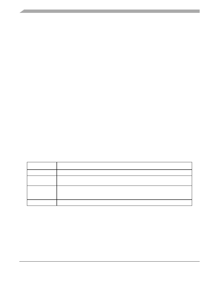
Table 5. Parameter classifications
Classification tag
Tag description
P
Those parameters are guaranteed during production testing on each individual device.
C
Those parameters are achieved by the design characterization by measuring a statistically
relevant sample size across process variations.
T
Those parameters are achieved by design characterization on a small sample size from typical
devices under typical conditions unless otherwise noted. All values shown in the typical column
are within this category.
D
Those parameters are derived mainly from simulations.
相關PDF資料 |
PDF描述 |
|---|---|
| MPC5646CF0MMJ8 | 32-BIT, FLASH, 80 MHz, MICROCONTROLLER, PBGA256 |
| MPC5646CF0CMJ8 | 32-BIT, FLASH, 80 MHz, MICROCONTROLLER, PBGA256 |
| MPC5646CF0MMJ8R | 32-BIT, FLASH, 80 MHz, MICROCONTROLLER, PBGA256 |
| MPC5646CF0VLT1 | 32-BIT, FLASH, 120 MHz, MICROCONTROLLER, PQFP208 |
| MPC5646CF0VLU1R | 32-BIT, FLASH, 120 MHz, MICROCONTROLLER, PQFP176 |
相關代理商/技術參數(shù) |
參數(shù)描述 |
|---|---|
| MPC564AADPT176 | 功能描述:開發(fā)板和工具包 - 其他處理器 ANDORRA ADAPT RoHS:否 制造商:Freescale Semiconductor 產品:Development Systems 工具用于評估:P3041 核心:e500mc 接口類型:I2C, SPI, USB 工作電源電壓: |
| MPC564AADPT208 | 制造商:Freescale Semiconductor 功能描述:ANDORRA ADAPSOLDERED |
| MPC564AKIT176 | 功能描述:開發(fā)板和工具包 - 其他處理器 ANDORRA 176QFP KIT RoHS:否 制造商:Freescale Semiconductor 產品:Development Systems 工具用于評估:P3041 核心:e500mc 接口類型:I2C, SPI, USB 工作電源電壓: |
| MPC564AKIT176S | 制造商:Freescale Semiconductor 功能描述:MPC564XA 176 LQFP SOCKET EVAL KIT 制造商:Freescale Semiconductor 功能描述:MPC564XA, 176 LQFP SOCKET, EVAL KIT |
| MPC564AKIT208 | 制造商:Freescale Semiconductor 功能描述:ANDORRA 208BGA KIT |
發(fā)布緊急采購,3分鐘左右您將得到回復。