- 您現(xiàn)在的位置:買賣IC網(wǎng) > PDF目錄374488 > MOR283R3S (CRANE ELECTRONICS INC) DC/DC CONVERTERS 28 VOLT INPUT PDF資料下載
參數(shù)資料
| 型號: | MOR283R3S |
| 廠商: | CRANE ELECTRONICS INC |
| 元件分類: | 基準電壓源/電流源 |
| 英文描述: | DC/DC CONVERTERS 28 VOLT INPUT |
| 中文描述: | 1-OUTPUT 66 W DC-DC REG PWR SUPPLY MODULE |
| 封裝: | MODULE-12 |
| 文件頁數(shù): | 6/16頁 |
| 文件大?。?/td> | 431K |
| 代理商: | MOR283R3S |
6
MOR SERIES
120 WATT
S
YNC
I
N AND
S
YNC
O
UT
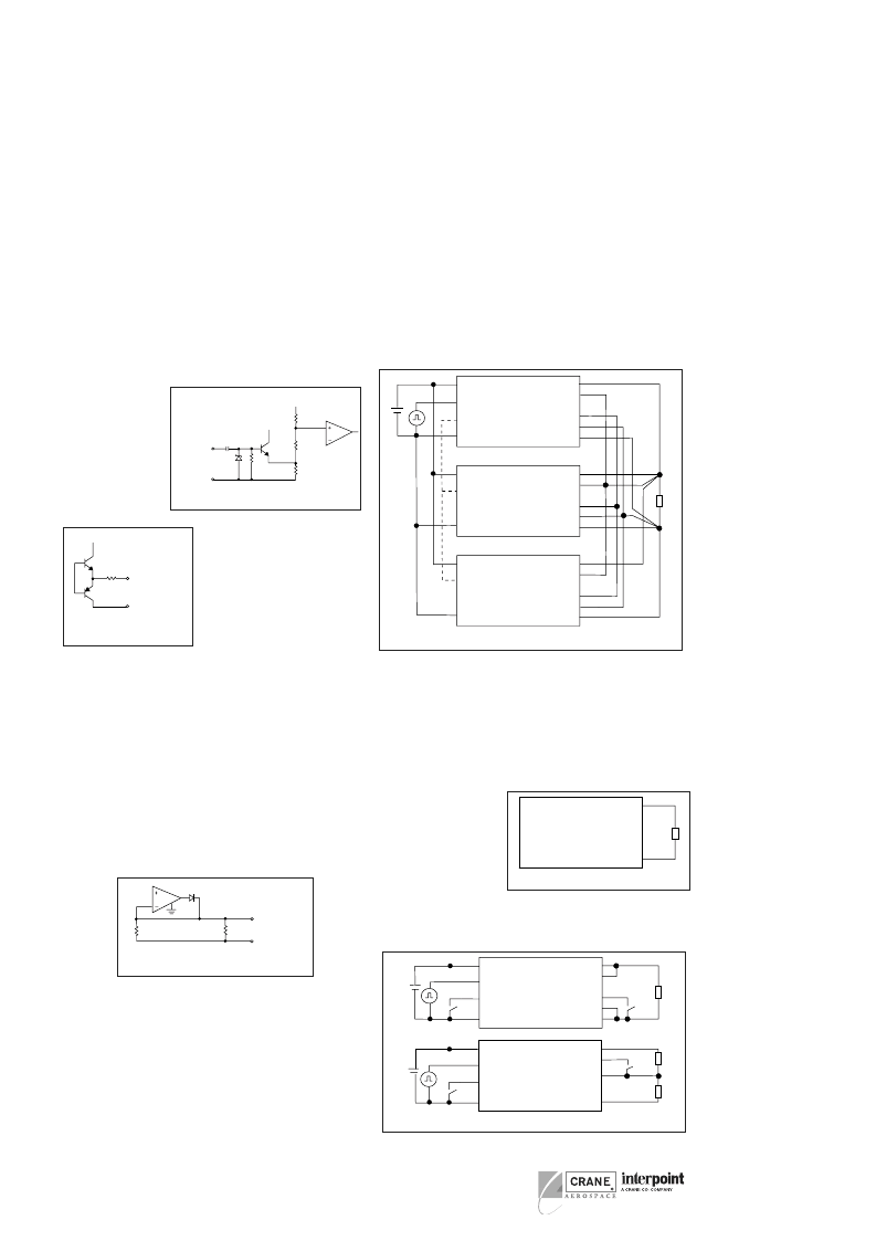
The MOR converters
can be synchronized to
the system clock by
applying a TTL compat-
ible sync signal to the
Sync In pin. Sync Out
can be used to synchro-
nize other components
to the MOR converter
’
s
switching frequency.
DC/DC C
ONVERTERS
The frequency range for external
synchronization is 525 to 625 kHz.
The requirements for an external
signal are 15% to 50% duty cycle,
0
≤
L
≤
0.8 V and 4.5
≤
H
≤
9 V.
Both Sync In and Sync Out are
referenced to input common. Sync
In should be grounded to input
common if not used.
P
OSITIVE
S
ENSE
, S
ENSE
R
ETURN
A special remote sensing feature maintains the desired output
voltage at the load. When this feature is not used, connect the
sense lines to their respective output terminals. Remote sensing is
available on single output models only. See Figure 12. Do not
exceed 110% of Vout and maximum output power.
S
HARE
(P
ARALLELING
)
By using the Share pin, up to five single or dual converters may be
paralleled for a total output power of over 500 watts (90% Pout /
converter, max.). The converters will share within 10% of each
other at 25 to 90% rated power. MOR converters feature true n+1
redundancy for reliability in critical applications. See Figure 9 for
the proper connections.
All Positive Outputs and Positive Senses should be connected to
a common point. All Negative Outputs and Sense Returns should
be connected to a common point. The Share pin is referenced to
Sense Return. Leave the share pin floating (unconnected) if not
used.
P
OSITIVE
O
UTPUT
, N
EGATIVE
O
UTPUT
AND
O
UTPUT
C
OMMON
Output current is limited to 125% of maximum specified current
under short circuit or load fault conditions.
Single output models operate from no load to full load. Dual output
models with balanced loads operate from no load to full load. For
dual models with unbalanced loads, at least 10% of the total output
power must be drawn
from the positive output
at all times, however, the
negative output does not
require a minimum load.
See note 7, cross regula-
tion, under the Electrical
Characteristics Tables.
Dual outputs may be
“
stacked
”
to double the
output voltage.
T
YPICAL
C
ONNECTIONS
+
Positive Input
1
6
5
2
7
10
11
9
8
7
10
11
9
8
7
10
11
9
8
Sync In
Sync Out
Input Common
Positive Output
Positive Sense
Share
Sense Return
Output common
Positive Output
Positive Sense
Sense Return
Output common
Positive Output
Positive Sense
Sense Return
Output common
Share
Share
–
28V
Positive Input
1
6
5
2
Sync In
Sync Out
Input Common
Positive Input
1
6
5
2
Sync In
Sync Out
Input Common
F
IGURE
10: P
ARALLELING
–
+
Load
Positive Input
1
6
4
2
7
10
12
9
8
28V
Sync In
Inhbit 1
Input Common
Positive Output
Positive Sense
Inhibit 2
Sense Return
Output Common
MOR
Single
Output
–
+
Load
Positive Input
1
6
4
2
7
12
8
9
28V
Sync In
Inhbit 1
Input Common
Positive Output
Inhibit 2
Output Common
Negative Output
MOR
Dual
Output
Load
0
F
IGURE
12: C
ONNECTIONS
–
+
Load
Positive Input
1
7
8
9
Input Common
Positive Output
Inhibit 2
Output Common
Negative Output
MOR
Dual Output
2
F
IGURE
11:“S
TACKED
” O
UTPUT
~
~
Sync In
Input
Common
5V
V
CC
330 pF
1.8 k
1 k
10 k
10 k
~
Sync Out
Input
Common
V
CC
200
F
IGURE
7: S
YNC
I
N
F
IGURE
8: S
YNC
O
UT
Share
Sense
Return
10 k
260 k
F
IGURE
9: S
HARE
相關(guān)PDF資料 |
PDF描述 |
|---|---|
| MP10005 | TECHNICAL SPECIFICATIONS OF SINGLE-PHASE SILICON BRIDGE RECTIFIER VOLTAGE RANGE - 50 to 1000 Volts |
| MP1000 | 10A BRIDGE RECTIFIER |
| MP1000 | Silicon Bridge Rectifiers |
| MP1001 | Silicon Bridge Rectifiers |
| MP1002 | Silicon Bridge Rectifiers |
相關(guān)代理商/技術(shù)參數(shù) |
參數(shù)描述 |
|---|---|
| MOR283R3S/883 | 制造商:CRANE 制造商全稱:CRANE 功能描述:MOR Single and Dual DC/DC Converters |
| MOR283R3S/ES | 制造商:CRANE 制造商全稱:CRANE 功能描述:MOR Single and Dual DC/DC Converters |
| MOR283R3S_10 | 制造商:INTERPOINT 制造商全稱:INTERPOINT 功能描述:Parallel operation with current share, up to 5 units (540 watts) |
| MOR283R3SV | 制造商:CRANE 制造商全稱:CRANE 功能描述:MOR Single and Dual DC/DC Converters |
| MOR283R3SV/883 | 制造商:CRANE 制造商全稱:CRANE 功能描述:MOR Single and Dual DC/DC Converters |
發(fā)布緊急采購,3分鐘左右您將得到回復(fù)。