- 您現(xiàn)在的位置:買賣IC網 > PDF目錄384742 > MMB0207 (Vishay Intertechnology,Inc.) Professional MELF Resistors PDF資料下載
參數(shù)資料
| 型號: | MMB0207 |
| 廠商: | Vishay Intertechnology,Inc. |
| 英文描述: | Professional MELF Resistors |
| 中文描述: | 專業(yè)MELF電阻 |
| 文件頁數(shù): | 1/13頁 |
| 文件大?。?/td> | 212K |
| 代理商: | MMB0207 |
Professional MELF Resistors
www.vishay.com
12
For technical questions contact:
ff3bresistors@vishay.com
Document Number: 28713
Revision: 18-Jul-06
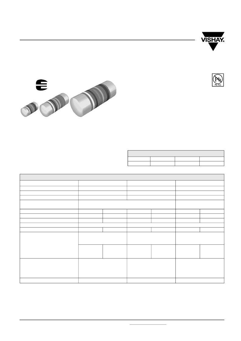
MMU 0102, MMA 0204, MMB 0207 - Professional
Vishay Beyschlag
FEATURES
Approved according to EN 140401-803
Advanced thin film technology
Excellent overall stability: exceeds Class 0.25
Force fitted steel caps, tin plated on nickel barrier
Pure Sn termination on Ni barrier layer
Compatible with lead (Pb)-free and lead containing
soldering processes
Lead (Pb)-free and RoHS compliant
APPLICATIONS
Automotive
Telecommunication
Industrial
Medical equipment.
METRIC SIZE
DIN:
CECC:
0102
0204
0207
RC 2211M
RC 3715M
RC 6123M
MMU 0102, MMA 0204 and MMB 0207 professional thin film
MELF resistors are the perfect choice for most fields of
modern professional electronics where reliability and stability
is of major concern. The typical applications in the fields of
automotive, telecommunication and medical equipment
reflect the outstanding level of proven reliability.
Note:
These resistors do not feature a limited lifetime when operated within the permissible limits. However, resistance value drift increasing over
operating time may result in exceeding a limit acceptable to the specific application, thereby establishing a functional lifetime.
1)
The power dissipation on the resistor generates a temperature rise against the local ambient, depending on the heatflow support of the
printed-circuit board (thermal resistance). The rated dissipation applies only if the permitted film temperature is not exceeded. Furthermore, a
high level of ambient temperature or of power dissipation may raise the temperature of the solder joint, hence special solder alloys or board
materials may be required to maintain the reliability of the assembly.
2)
Specified power rating requires dedicated heat-sink pads.
3)
Film temperatures above the specified range may be permissible, e.g. 175 °C. Please contact the factory for details.
TECHNICAL SPECIFICATIONS
DESCRIPTION
CECC size
Resistance range
Resistance tolerance
MMU 0102
RC 2211M
0.22
Ω
to 2.21 M
Ω
± 5 %; ± 2 %; ± 1 %; ± 0.5 %
MMA 0204
RC 3715M
0.22
Ω
to 10 M
Ω
± 5 %; ± 1 %; ± 0.5 %
MMB 0207
RC 6123M
0.1
Ω
to 15 M
Ω
± 5 %; ± 2 %; ± 1 %; ± 0.5 %
± 100 ppm/K; ± 50 ppm/K;
± 25 ppm/K
standard
55/125/56
0.4 W
300 V
125 °C
Temperature coefficient
± 50 ppm/K; ± 25 ppm/K
Operation mode
Climatic category (LCT/UCT/days)
Rated dissipation,
P
701)
Operating voltage,
U
max
AC/DC
Film temperature
3)
Max. resistance change at
P
70
for resistance range,
|
Δ
R
/
R
| max., after:
1000 h
8000 h
225 000 h
Permissible voltage
against ambient (insulation):
1 minute;
U
ins
continuous
Failure rate
standard
55/125/56
0.2 W
power
55/155/56
0.3 W
standard
55/125/56
0.25 W
power
55/155/56
0.4 W
power
55/155/56
1.0 W
2)
150 V
200 V
125 °C
155 °C
125 °C
155 °C
155 °C
0.22
Ω
to 221 k
Ω
0.22
Ω
to 332 k
Ω
0.22
Ω
to 1 M
Ω
≤
0.15 %
≤
0.3 %
≤
1 %
≤
0.25 %
≤
0.5 %
-
≤
0.15 %
≤
0.3 %
≤
1 %
≤
0.25 %
≤
0.5 %
-
≤
0.15 %
≤
0.3 %
≤
1 %
≤
0.25 %
≤
0.5 %
-
200 V
75 V
≤
2 x 10
-9
/h
300 V
75 V
500 V
75 V
≤
0.7 x 10
-9
/h
≤
0.7 x 10
-9
/h
相關PDF資料 |
PDF描述 |
|---|---|
| MMUN2215RLT1 | Bias Resistor Transistor |
| MMUN2213RLT1 | Bias Resistor Transistor |
| MMVL3700T1 | High Voltage Silicon Pin Diode |
| MMVL809T1 | Silicon Tuning Diode |
| MNA-6 | Monolithic Amplifiers High Directivity, 50з, 0.5 to 5.9 GHz |
相關代理商/技術參數(shù) |
參數(shù)描述 |
|---|---|
| MMB-0207 | 制造商:VISHAY 制造商全稱:Vishay Siliconix 功能描述:Professional MELF Resistors |
| MMB0207 SampleBook | 制造商:Vishay Intertechnologies 功能描述:Bulk |
| MMB02070B0000DB000 | 制造商:VISHAY 制造商全稱:Vishay Siliconix 功能描述:MMU 0102, MMA 0204, MMB 0207 - Professional |
| MMB02070B0000DB200 | 制造商:VISHAY 制造商全稱:Vishay Siliconix 功能描述:MMU 0102, MMA 0204, MMB 0207 - Professional |
| MMB02070B0000DB300 | 制造商:VISHAY 制造商全稱:Vishay Siliconix 功能描述:MMU 0102, MMA 0204, MMB 0207 - Professional |
發(fā)布緊急采購,3分鐘左右您將得到回復。