- 您現(xiàn)在的位置:買賣IC網(wǎng) > PDF目錄383574 > MCH15 (Rohm CO.,LTD.) Multi-layer Ceramic Chip Capacitors(多層陶瓷電容) PDF資料下載
參數(shù)資料
| 型號: | MCH15 |
| 廠商: | Rohm CO.,LTD. |
| 英文描述: | Multi-layer Ceramic Chip Capacitors(多層陶瓷電容) |
| 中文描述: | 多層陶瓷芯片電容器(多層陶瓷電容) |
| 文件頁數(shù): | 4/10頁 |
| 文件大小: | 119K |
| 代理商: | MCH15 |
MCH15
Ceramic capacitors
!
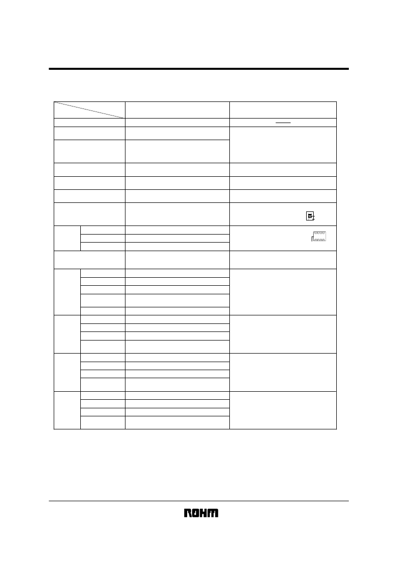
Characteristics
A (C0G)
-55
C ~
125
C
Temperature characteristics
Item
Operating temperature
Nominal capacitance (C)
Dissipation factor (tan
δ
)
Insulation resistance (IR)
Withstanding voltage
Temperature characteristics
Terminal adherence
Resistance
to vibration
Solderability
Resistance
to soldering
heat
Temperature
cycling
High-
temperature
load test
Humidity load
test
Must be within the specified tolerance range.
100/(400+20C)% or less: Less than 30 pF
0.1% or less: 30 pF or larger
10,000 M
or 500 M
μ
F,
whichever is smaller
The insulation must not be damaged.
Within 0
±
30ppm/
C
No detachment or signs of detachment.
There must be no mechanical damage.
Must be within initial tolerance.
Must satisfy initial specified value.
At least 3/4 of the surface of the two terminals
must be covered with new solder.
There must be no mechanical damage.
±
2.5% or
±
0.25 pF, whichever is larger.
Must satisfy initial specified value.
10,000 M
or 500 M
μ
F,
whichever is smaller
The insulation must not be damaged.
There must be no mechanical damage.
±
2.5% or
±
0.25 pF, whichever is larger.
Must satisfy initial specified value.
10,000 M
or 500 M
μ
F,
whichever is smaller
There must be no mechanical damage.
±
7.5% or
±
0.75 pF, whichever is larger.
0.5% or less
500 M
or 25 M
μ
F,
whichever is smaller
There must be no mechanical damage.
1,000 M
or 50 M
μ
F,
whichever is smaller
±
3.0% or
±
0.3 pF, whichever is larger.
0.3% or less
Appearance
Rate of capacitance change
tan
δ
Appearance
Rate of capacitance change
tan
δ
Insulation resistance
Withstanding voltage
Appearance
Rate of capacitance change
tan
δ
Insulation resistance
Appearance
Rate of capacitance change
tan
δ
Insulation resistance
Appearance
Rate of capacitance change
tan
δ
Insulation resistance
Test methods/conditions
(based on JIS C 5102)
Based on paragraph 7.8 and paragraph 9
Measured at room temperature and standard humidity,
1000pF or less Measurement frequency
Measurement voltage
Over 1000pF
Measurement voltage
Measurement frequency
Based on paragraph 7.6
Measurement is made after rated voltage is applied for 60
±
5s.
Based on paragraph 7.1
Apply 300% of the rated voltage for 1 to 5s then measure.
The temperature coefficients in table 12, paragraph 7.12 are
calculated at 20
C
and high temperature.
Based on paragraph 8.11. 2.
Apply 5N (0.51 kg
f) for 10
±
1s in the
direction indicated by the arrow.
Capacitor
Test board
Pressure (5N)
Chip is mounted to a board in the manner
shown on the right, subjected to vibration
(type A in paragraph 8.2), and measured
24
±
2 hrs. later.
Board
Based on paragraph 8.13
Soldering temperature
Soldering time
Based on paragraph 8.14.
Soldering temperature
Soldering time
Preheating
Based on paragraph 9.3
Number of cycles: 10
Capacitance measured after 24
±
2 hrs.
Test temperature
Relative humidity
Applied voltage
Test time
Capacitance measured after 24
±
2 hrs.
Based on paragraph 9.9
Test temperature
Applied voltage
Test time
Capacitance measured after 24
±
2 hrs.
Based on paragraph 9.10
Class 1 (For thermal compensation)
: 1
±
0.1MHz
: 1
±
0.1Vrms.
: 1
±
0.1kHz
: 1
±
0.1Vrms.
: 235
±
5
C
: 2
±
0.5s
: 260
±
5
C
: 5
±
0.5s
: 150
±
10
C
for 1 to 2 min.
: 40
±
2
C
: 90% to 95%
: rated voltage
: 500 to 524 hrs.
: Max. operating temp.
: rated voltage x 200%
: 1,000 to 1,048 hrs.
*The design and specifications are subject to change without prior notice. Before ordering or using, please check the latest technical specification.
相關(guān)PDF資料 |
PDF描述 |
|---|---|
| MCH183AN103CC | 1608(0603)Size chip capacitors |
| MCH183AN103CK | 1608(0603)Size chip capacitors |
| MCH183AN103CL | 1608(0603)Size chip capacitors |
| MCH183AN103DC | 1608(0603)Size chip capacitors |
| MCH183AN103DK | 1608(0603)Size chip capacitors |
相關(guān)代理商/技術(shù)參數(shù) |
參數(shù)描述 |
|---|---|
| MCH152A103C | 制造商:ROHM 制造商全稱:Rohm 功能描述:1005(0402)Size chip capacitors |
| MCH152A103D | 制造商:ROHM 制造商全稱:Rohm 功能描述:1005(0402)Size chip capacitors |
| MCH152A103J | 制造商:ROHM 制造商全稱:Rohm 功能描述:1005(0402)Size chip capacitors |
| MCH152A103K | 制造商:ROHM 制造商全稱:Rohm 功能描述:1005(0402)Size chip capacitors |
| MCH152A103Z | 制造商:ROHM 制造商全稱:Rohm 功能描述:1005(0402)Size chip capacitors |
發(fā)布緊急采購,3分鐘左右您將得到回復(fù)。