- 您現(xiàn)在的位置:買賣IC網(wǎng) > PDF目錄385573 > MC7918 (ON SEMICONDUCTOR) 1.0 A Negative Voltage Regulators(1.0 A 負向穩(wěn)壓器) PDF資料下載
參數(shù)資料
| 型號: | MC7918 |
| 廠商: | ON SEMICONDUCTOR |
| 元件分類: | 基準電壓源/電流源 |
| 英文描述: | 1.0 A Negative Voltage Regulators(1.0 A 負向穩(wěn)壓器) |
| 中文描述: | 1.0負電壓穩(wěn)壓器(1.0甲負向穩(wěn)壓器) |
| 文件頁數(shù): | 6/16頁 |
| 文件大?。?/td> | 124K |
| 代理商: | MC7918 |
MC7900 Series
http://onsemi.com
6
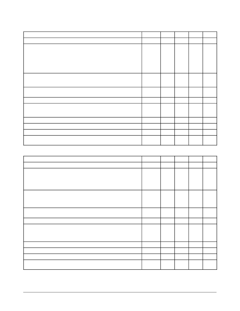
MC7915C
ELECTRICAL CHARACTERISTICS
(V
I
= –23 V, I
O
= 500 mA, 0
°
C < T
J
< +125
°
C, unless otherwise noted.)
Characteristics
Symbol
Min
Typ
Max
Unit
Output Voltage (T
J
= +25
°
C)
V
O
–14.4
–15
–15.6
Vdc
Line Regulation (Note 5)
(T
J
= +25
°
C, I
O
= 100 mA)
–17.5 Vdc
≥
V
I
≥
–30 Vdc
–20 Vdc
≥
V
I
≥
–26 Vdc
(T
J
= +25
°
C, I
O
= 500 mA)
–17.5 Vdc
≥
V
I
≥
–30 Vdc
–20 Vdc
≥
V
I
≥
–26 Vdc
Reg
line
–
–
–
–
14
6.0
57
27
150
75
300
150
mV
Load Regulation, T
J
= +25
°
C (Note 5)
5.0 mA
≤
I
O
≤
1.5 A
250 mA
≤
I
O
≤
750 mA
Reg
load
–
–
68
25
300
150
mV
Output Voltage
–17.5 Vdc
≥
V
I
≥
–30 Vdc, 5.0 mA
≤
I
O
≤
1.0 A, P
≤
15 W
V
O
–14.25
–
–15.75
Vdc
Input Bias Current (T
J
= +25
°
C)
I
IB
–
4.4
8.0
mA
Input Bias Current Change
–17.5 Vdc
≥
V
I
≥
–30 Vdc
5.0 mA
≤
I
O
≤
1.5 A
I
IB
–
–
–
–
1.0
0.5
mA
Output Noise Voltage (T
A
= +25
°
C, 10 Hz
≤
f
≤
100 kHz)
V
n
–
90
–
μ
V
Ripple Rejection (I
O
= 20 mA, f = 120 Hz)
RR
–
60
–
dB
Dropout Voltage (I
O
= 1.0 A, T
J
= +25
°
C)
V
I
–V
O
–
2.0
–
Vdc
Average Temperature Coefficient of Output Voltage
I
O
= 5.0 A, 0
°
C
≤
T
J
≤
+125
°
C
V
O
/
T
–
–1.0
–
mV/
°
C
MC7915AC
ELECTRICAL CHARACTERISTICS
(V
I
= –23 V, I
O
= 500 mA, 0
°
C < T
J
< +125
°
C, unless otherwise noted.)
Characteristics
Symbol
Min
Typ
Max
Unit
Output Voltage (T
J
= +25
°
C)
V
O
–14.7
–15
–15.3
Vdc
Line Regulation (Note 5)
–20 Vdc
≥
V
I
≥
–26 Vdc, I
O
= 1.0 A, T
J
= +25
°
C
–20 Vdc
≥
V
I
≥
–26 Vdc, I
O
= 1.0 A,
–17.9 Vdc
≥
V
I
≥
–30 Vdc, I
O
= 500 mA
–17.5 Vdc
≥
V
I
≥
–30 Vdc, I
O
= 1.0 A, T
J
= +25
°
C
Reg
line
–
–
–
–
27
57
57
57
75
150
150
150
mV
Load Regulation (Note 5)
5.0 mA
≤
I
O
≤
1.5 A, T
J
= +25
°
C
250 mA
≤
I
O
≤
750 mA
5.0 mA
≤
I
O
≤
1.0 A
Reg
load
–
–
–
68
25
40
150
75
150
mV
Output Voltage
–17.9 Vdc
≥
V
I
≥
–30 Vdc, 5.0 mA
≤
I
O
≤
1.0 A, P
≤
15 W
V
O
–14.4
–
–15.6
Vdc
Input Bias Current
I
IB
–
4.4
8.0
mA
Input Bias Current Change
–17.5 Vdc
≥
V
I
≥
–30 Vdc
5.0 mA
≤
I
O
≤
1.0 A
5.0 mA
≤
I
O
≤
1.5 A, T
J
= +25
°
C
I
IB
–
–
–
–
–
–
0.8
0.5
0.5
mA
Output Noise Voltage (T
A
= +25
°
C, 10 Hz
≤
f
≤
100 kHz)
V
n
–
90
–
μ
V
Ripple Rejection (I
O
= 20 mA, f = 120 Hz)
RR
–
60
–
dB
Dropout Voltage (I
O
= 1.0 A, T
J
= +25
°
C)
V
I
–V
O
–
2.0
–
Vdc
Average Temperature Coefficient of Output Voltage
I
O
= 5.0 mA, 0
°
C
≤
T
J
≤
+125
°
C
V
O
/
T
–
–1.0
–
mV/
°
C
5. Load and line regulation are specified at constant junction temperature. Changes in V
O
due to heating effects must be taken into account
separately. Pulse testing with low duty cycle is used.
相關(guān)PDF資料 |
PDF描述 |
|---|---|
| MC79L00A | 100 mA Negative Voltage Regulators(三端小電流負固定電壓的穩(wěn)壓器) |
| MC79L05 | 100 mA Negative Voltage Regulators(三端小電流負固定電壓的穩(wěn)壓器) |
| MC79L12 | 100 mA Negative Voltage Regulators(三端小電流負固定電壓的穩(wěn)壓器) |
| MC79L15 | 100 mA Negative Voltage Regulators(三端小電流負固定電壓的穩(wěn)壓器) |
| MC79L18 | 100 mA Negative Voltage Regulators(100 mA負向穩(wěn)壓器) |
相關(guān)代理商/技術(shù)參數(shù) |
參數(shù)描述 |
|---|---|
| MC7918ACD2T | 制造商:MOTOROLA 制造商全稱:Motorola, Inc 功能描述:THREE-TERMINAL NEGATIVE FIXED VOLTAGE REGULATORS |
| MC7918ACT | 制造商:MOTOROLA 制造商全稱:Motorola, Inc 功能描述:THREE-TERMINAL NEGATIVE FIXED VOLTAGE REGULATORS |
| MC7918BD2T | 制造商:MOTOROLA 制造商全稱:Motorola, Inc 功能描述:THREE-TERMINAL NEGATIVE FIXED VOLTAGE REGULATORS |
| MC7918BT | 制造商:MOTOROLA 制造商全稱:Motorola, Inc 功能描述:THREE-TERMINAL NEGATIVE FIXED VOLTAGE REGULATORS |
| MC7918CD2T | 制造商:MOTOROLA 制造商全稱:Motorola, Inc 功能描述:THREE-TERMINAL NEGATIVE VOLTAGE REGULATORS |
發(fā)布緊急采購,3分鐘左右您將得到回復(fù)。