- 您現(xiàn)在的位置:買(mǎi)賣(mài)IC網(wǎng) > PDF目錄371036 > MC44724 (Motorola, Inc.) Digital Video Encoder PDF資料下載
參數(shù)資料
| 型號(hào): | MC44724 |
| 廠商: | Motorola, Inc. |
| 英文描述: | Digital Video Encoder |
| 中文描述: | 數(shù)字視頻編碼器 |
| 文件頁(yè)數(shù): | 6/39頁(yè) |
| 文件大小: | 518K |
| 代理商: | MC44724 |
第1頁(yè)第2頁(yè)第3頁(yè)第4頁(yè)第5頁(yè)當(dāng)前第6頁(yè)第7頁(yè)第8頁(yè)第9頁(yè)第10頁(yè)第11頁(yè)第12頁(yè)第13頁(yè)第14頁(yè)第15頁(yè)第16頁(yè)第17頁(yè)第18頁(yè)第19頁(yè)第20頁(yè)第21頁(yè)第22頁(yè)第23頁(yè)第24頁(yè)第25頁(yè)第26頁(yè)第27頁(yè)第28頁(yè)第29頁(yè)第30頁(yè)第31頁(yè)第32頁(yè)第33頁(yè)第34頁(yè)第35頁(yè)第36頁(yè)第37頁(yè)第38頁(yè)第39頁(yè)
MC44724/5 Rev 0.21 03/25/97
No.
This document contains information on a new product. Specifications and information herein are subject to change without notice.
Video Timing / Sync Generator
The DVE outputs PAL-B,D,G,H,I, PAL-N, PAL-M or NTSC-M standard video signals.
The DVE sync generator can be operated in two modes, master or slave.
In master mode, the DVE generates all the correct Horizontal and Vertical or Frame sync signals
internally, or it is output Csync signal through the EXT pin(C/Fsync).
In slave mode, the DVE derives the sync signals from the Bit-Parallel input data stream Start Active
Video (SAV) and End Active Video (EAV) data packet information. Sync signals are output on the
Hsync and F/Vsync or EXT pins and can be programmed for positive or negative polarity. The phase of
Hsync can also be controlled.
Also, the DVE allows more two slave modes. One is H/Vsync slave, and the aother is H/Fsync slave
mode.
Vertical Blanking corresponds to the following lines.
625/50 624-22 311-335 ITU-R line numbering
525/60 1-19 264-282 SMPTE line numbering
(see figures 3,4,5,6,7,8,9,10, and 11 for sub-address register descriptions.)
Input Data Format
The input digital video is in accord with the ITU-R Rec.656 and SMPTE 125M standards. It is an two 8-bit
or 16-bit multiplexed 4:2:2 ((CB,Y,CR)Y) data stream. Samples are latched on the rising edge of the clock
signal. Data is input on pins
DVIN[ 7 : 0 ]
and
TP[ 8 : 1 ]
(see figures 3 and 4 for sub-address register descriptions.)
6
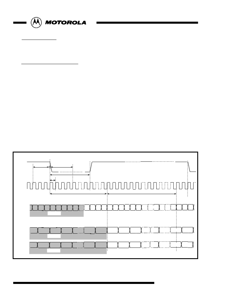
Fig 3 : Digital Input Timing(525/60 system) in Master Mode
70(hex){[1:0]=01}
1440T
Hsync phase
sub-address71[2:0]
+4T delay
Hsync
clock
128T
T
244T
Hsync polarity
sub-address71[5]
-3T delay
DVIN0~7
Cr
718
Cb
718
Y
718
Y
719
00
00
FF
Cb
2
Cr
0
Cb
0
Y
0
Y
1
Y
2
INVALID
00
00
XY
FF
Y
718
Y
719
TP1~8
Cr
718
Cb
718
Cb
2
Cr
0
Cb
0
INVALID
DVIN0~7
Y2
Y
1
Y
0
INVALID
16-bit input mode
8-bit input mode
Cb
718
Cr
718
Cr
2
Cr
0
Cb
0
or
相關(guān)PDF資料 |
PDF描述 |
|---|---|
| MC44725VFU | Digital Video Encoder |
| MC44BC380 | VHF/ UHF ANTENNA BOOSTER/SPLITTER IC |
| MC54-74HC175 | Quad D Flip-Flop with Common Clock and Reset |
| MC54-74HC175 | Quad D Flip-Flop with Common Clock and Reset |
| MC54-74HC390 | Dual 4-Stage Binary Ripple Counter with ±2 and ±5 Sections |
相關(guān)代理商/技術(shù)參數(shù) |
參數(shù)描述 |
|---|---|
| MC44724A | 制造商:MOTOROLA 制造商全稱:Motorola, Inc 功能描述:Advanced Digital Video Encoder |
| MC44724AVFU | 制造商:Rochester Electronics LLC 功能描述: 制造商:Freescale Semiconductor 功能描述: |
| MC44724VFU | 制造商:MOTOROLA 制造商全稱:Motorola, Inc 功能描述:Digital Video Encoder |
| MC44725A | 制造商:MOTOROLA 制造商全稱:Motorola, Inc 功能描述:Advanced Digital Video Encoder |
| MC44725VFU | 制造商:MOTOROLA 制造商全稱:Motorola, Inc 功能描述:Digital Video Encoder |
發(fā)布緊急采購(gòu),3分鐘左右您將得到回復(fù)。