- 您現(xiàn)在的位置:買賣IC網(wǎng) > PDF目錄371036 > MC44302ADW (MOTOROLA INC) ADVANCED MULTI-STANDARD VIDEO/SOUND IF PDF資料下載
參數(shù)資料
| 型號: | MC44302ADW |
| 廠商: | MOTOROLA INC |
| 元件分類: | 消費家電 |
| 英文描述: | ADVANCED MULTI-STANDARD VIDEO/SOUND IF |
| 中文描述: | SPECIALTY CONSUMER CIRCUIT, PDSO28 |
| 封裝: | PLASTIC, SO-28 |
| 文件頁數(shù): | 19/28頁 |
| 文件大小: | 612K |
| 代理商: | MC44302ADW |
第1頁第2頁第3頁第4頁第5頁第6頁第7頁第8頁第9頁第10頁第11頁第12頁第13頁第14頁第15頁第16頁第17頁第18頁當前第19頁第20頁第21頁第22頁第23頁第24頁第25頁第26頁第27頁第28頁
MC44302A
19
MOTOROLA ANALOG IC DEVICE DATA
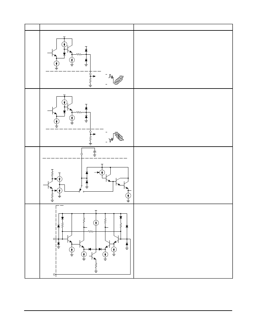
PIN FUNCTION DESCRIPTION (continued)
Pin No.
Description
Equivalent Internal Circuit
5
VCC
Negative Video Output
VCC
60
1.0 mA
2.0 k
6
3.4
1.2
Negative Video Output
Negative going video appears at this output and it is intended to
drive a sync separator. Positive going video will appear at this
output when Pin 3 is grounded. This feature provides a simple
means for descrambling the video signal in systems that use
alternate line video inversion. Refer to the description of Pin 3. The
video output is designed to drive a resistive load that is in the range
of 2.0 k
. Lower resistance values will tend to increase output
distortion.
6
VCC
Positive Video Output
VCC
60
1.0 mA
2.0 k
6
3.4
1.2
Positive Video Output
Positive going video appears at this output and is intended to drive
the luma and chroma channels. Negative going video will appear
at this output when Pin 3 is grounded. This feature provides a
simple means for descrambling the video signal in systems that
use alternate line video inversion. Refer to the description of Pin 3.
The positive going video signal always contains white spot
inversion whether it appears at output Pins 5 or 6. The video
output is designed to drive a resistive load that is in the range of
2.0 k
. Lower resistance values could increase output distortion.
7
7
Sound AFT Filter/
Peak White Filter
VCC
VCC
0 to
±
300
μ
A
10
VCC
SECAM
PAL
NTSC
Sound AFT Filter/Peak White Filter
A capacitor connected from this pin to ground is used to adjust the
sound AFT time constant in PAL and NTSC modes, and video
peak white AGC time constant in SECAM mode. The sound AFT
filter voltage controls the internal tuning capacitance that is placed
across the sound quadrature coil at Pin 26. Refer to Figure 9.
8, 9
Video IF
Input
VCC
8
3.4 k
9
Video IF Input
These pins are the inputs to the video IF amplifier. The amplifier
consists of four ac coupled stages with an input sensitivity of
40
μ
V for a 2.2 Vpp video output swing. This sensitivity eliminates
the need for a preamplifier when used with suitable surface
acoustic waves or passive block filters. The IF block filter must be
located close to the IC package inputs to prevent unwanted pickup
and possible instability problems. The input lead lengths must be
kept short with a symmetrical printed circuit board layout.
相關PDF資料 |
PDF描述 |
|---|---|
| MC44302AP | ADVANCED MULTI-STANDARD VIDEO/SOUND IF |
| MC44353DTB | MULTI.STANDARD AND PAL/NTSC MODULATOR ICs |
| MC44353 | MULTI.STANDARD AND PAL/NTSC MODULATOR ICs |
| MC44355DTB | MULTI.STANDARD AND PAL/NTSC MODULATOR ICs |
| MC44354DTB | MULTI.STANDARD AND PAL/NTSC MODULATOR ICs |
相關代理商/技術(shù)參數(shù) |
參數(shù)描述 |
|---|---|
| MC44302AP | 制造商:MOTOROLA 制造商全稱:Motorola, Inc 功能描述:ADVANCED MULTI-STANDARD VIDEO/SOUND IF |
| MC4433 | 制造商:SHENZHENFREESCALE 制造商全稱:ShenZhen FreesCale Electronics. Co., Ltd 功能描述:P-Channel 30-V (D-S) MOSFET Fast switching speed |
| MC4435 | 制造商:SHENZHENFREESCALE 制造商全稱:ShenZhen FreesCale Electronics. Co., Ltd 功能描述:P-Channel 30-V (D-S) MOSFET Fast switching speed |
| MC44353 | 制造商:MOTOROLA 制造商全稱:Motorola, Inc 功能描述:MULTI.STANDARD AND PAL/NTSC MODULATOR ICs |
| MC44353DTB | 制造商:MOTOROLA 制造商全稱:Motorola, Inc 功能描述:MULTI.STANDARD AND PAL/NTSC MODULATOR ICs |
發(fā)布緊急采購,3分鐘左右您將得到回復。