- 您現(xiàn)在的位置:買(mǎi)賣(mài)IC網(wǎng) > PDF目錄382299 > MC1494 (ON SEMICONDUCTOR) LINEAR FOUR-QUADRANT MULTIPLIER INTEGRATED CIRCUIT PDF資料下載
參數(shù)資料
| 型號(hào): | MC1494 |
| 廠商: | ON SEMICONDUCTOR |
| 英文描述: | LINEAR FOUR-QUADRANT MULTIPLIER INTEGRATED CIRCUIT |
| 中文描述: | 線性四象限乘法器集成電路 |
| 文件頁(yè)數(shù): | 12/16頁(yè) |
| 文件大小: | 319K |
| 代理商: | MC1494 |
第1頁(yè)第2頁(yè)第3頁(yè)第4頁(yè)第5頁(yè)第6頁(yè)第7頁(yè)第8頁(yè)第9頁(yè)第10頁(yè)第11頁(yè)當(dāng)前第12頁(yè)第13頁(yè)第14頁(yè)第15頁(yè)第16頁(yè)

MC1494
12
MOTOROLA ANALOG IC DEVICE DATA
VO = 10 |VZ|
–10 V < VZ < 0 V
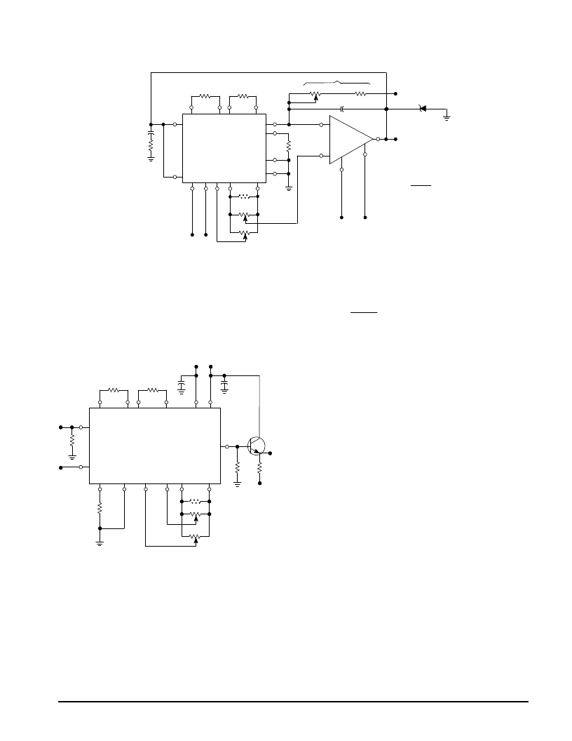
Figure 25. Square Root Circuit
30 k
62 k
11
12
7
8
RL
50 k
22 k
10pF
14
1
2
3
6
VO
+15 V
–15 V
MC1494
MC1741C
1N962B
(1N5241B)
(11V)
or
Equivalent
–15 V +15 V
P2 20 k
P3 20 k
51 k
2
10
9
3
6
16 k
+
+
+
–
VZ
5
15 13
4
10 pF
510
4
7
P4
The circuit of Figure 26 demonstrates the linear AGC
amplifier. The amplifier can handle 1.0 Vrms and exhibits a
gain of approximately 20 dB. It is AGC’d through a 60 dB
dynamic range with the application of an AGC voltage from
0 Vdc to 1.0 Vdc. The bandwidth of the amplifier is
determined by the load resistor and output stray capacitance.
For this reason, an emitter–follower buffer has been added to
extend the bandwidth in excess of 1.0 MHz.
Figure 26. Wideband Amplifier with Linear AGC
51 k
20 k
P2
20 k
P1
51 k
3.0 k
eo
14
–15 V
3.0 k
6.2 k
0.1
μ
F
8
11
12
7
5
15
–15 V+15 V
2
1
3
6
13
4
16 k
2N3946
(2N3904)
or Equivalent
+
+
ein
9
R
10
VAGC
MC1494
0.1
μ
F
Balanced Modulator
When two–time variant signals are used as inputs, the
resulting output is suppressed–carrier double–sideband
modulation. In terms of sinusoidal inputs, this can be seen in
the following equation:
VO = K(e1 cos
ω
mt) (e2 cos
ω
ct)
where
ω
m is the modulation frequency and
ω
c is the carrier
frequency. This equation can be expanded to show the
suppressed carrier or balanced modulation:
Ke1e2
2
Unlike many modulation schemes, which are nonlinear in
nature, the modulation which takes place when using the
MC1494 is linear. This means that for two sinusoidal inputs,
the output will contain only two frequencies, the sum and
difference, as seen in the above equation. There will be no
spectrum centered about the second harmonic of the carrier,
or any multiple of the carrier. For this reason, the filter
requirements of a modulation system are reduced to the
minimum. Figure 27 shows the MC1494 configuration to
perform this function.
Notice that the resistor values for RX, RY and RL have
been modified. This has been done primarily to increase the
bandwidth by lowering the output impedance of the MC1494
and then lowering RX and RY to achieve a gain of 1. The ec
can be as large as 1.0 V peak and em as high as 2.0 V peak.
No output offset adjust is employed since we are interested
only in the AC output components.
The input reisstors (R) are used to supply bias current to
the multiplier inputs as well as provide matching input
impedance. The output frequency range of this configuration
is determined by the 4.7 k
output impedance and capacitive
loading. Assuming a 6.0 pF load, the small–signal bandwidth
is 5.5 MHz.
The circuit of Figure 27 will provide at typical carrier
rejection of
≥
70 dB from 10 kHz to 1.5 MHz.
VO =
[cos(
ω
c+
ω
m
)
t
+
cos
(ω
c
±ω
m)t]
相關(guān)PDF資料 |
PDF描述 |
|---|---|
| MC1494P | OC-48/24/12/3 SONET SDH Multi-Rate Transceiver with Enhanced Jitter Tolerance 100-HTQFP -40 to 85 |
| MC1602-18 | Standard LCD Module |
| MC16A | 16 Lead Ceramic Small Outline Package NS Package Number MC16A |
| MC1DU256HACA-0QC00 | MultiMediaCard Specification |
| MC12U256NACA | MultiMediaCard Specification |
相關(guān)代理商/技術(shù)參數(shù) |
參數(shù)描述 |
|---|---|
| MC1494L | 制造商:Panasonic Industrial Company 功能描述:IC |
| MC1495BP | 制造商:Panasonic Industrial Company 功能描述:IC |
| MC1495D | 制造商:Panasonic Industrial Company 功能描述:IC |
| MC1495L | 制造商:Motorola Inc 功能描述: |
| MC1496BD | 功能描述:調(diào)節(jié)器/解調(diào)器 Balanced Mod/DeMod RoHS:否 制造商:Texas Instruments 封裝 / 箱體:PVQFN-N24 封裝:Reel |
發(fā)布緊急采購(gòu),3分鐘左右您將得到回復(fù)。