- 您現(xiàn)在的位置:買賣IC網(wǎng) > PDF目錄53721 > MBR3060PT (VISHAY SEMICONDUCTORS) 30 A, 60 V, SILICON, RECTIFIER DIODE, TO-247AD PDF資料下載
參數(shù)資料
| 型號(hào): | MBR3060PT |
| 廠商: | VISHAY SEMICONDUCTORS |
| 元件分類: | 整流器 |
| 英文描述: | 30 A, 60 V, SILICON, RECTIFIER DIODE, TO-247AD |
| 封裝: | PLASTIC, TO-3P, 3 PIN |
| 文件頁(yè)數(shù): | 1/3頁(yè) |
| 文件大小: | 55K |
| 代理商: | MBR3060PT |
MBR3035PT thru MBR3060PT
Vishay Semiconductors
formerly General Semiconductor
Document Number 88676
www.vishay.com
07-Feb-02
1
Dual Schottky Rectifiers
Reverse Voltage 35 to 60V
Forward Current 30A
Maximum Ratings & Thermal Characteristics Ratings at 25°C ambient temperature unless otherwise specified.
Parameter
Symbol
MBR3035PT MBR3045PT MBR3050PT MBR3060PT
Unit
Maximum repetitive peak reverse voltage
VRRM
35
45
50
60
V
Maximum working peak reverse voltage
VRWM
35
45
50
60
V
Maximum DC blocking voltage
VDC
35
45
50
60
V
Maximum average forward rectified current (See Fig. 1)
IF(AV)
30
A
Peak repetitive forward current per leg at TC = 105°C
(rated VR, square wave, 20 KHZ)
IFRM
30
A
Peak forward surge current, 8.3ms single half sine-wave
IFSM
200
A
superimposed on rated load (JEDEC Method)
Peak repetitive reverse surge current(1)
IRRM
2.0
1.0
A
Thermal resistance from junction to case per leg
R
θJC
1.4
°C/W
Voltage rate of change at (rated VR)
dv/dt
10,000
V/
s
Operating junction temperature range
TJ
– 65 to +150
°C
Storage temperature range
TSTG
– 65 to +175
°C
Electrical Characteristics Ratings at 25°C ambient temperature unless otherwise specified.
Parameter
Symbol
MBR3035PT MBR3045PT MBR3050PT MBR3060PT
Unit
Maximum instantaneous
IF = 20A, TC = 25°C
–
0.75
forward voltage per leg at:(2) IF = 20A, TC = 125°C
VF
0.60
0.65
V
IF = 30A, TC = 25°C
0.76
–
IF = 30A, TC = 125°C
0.72
–
Maximum instantaneous reverse current at
TC = 25°C
IR
1.0
5.0
mA
rated DC blocking voltage per leg(2)
TC = 125°C
60
100
Notes: (1) 2.0
s pulse width, f = 1.0 KHZ
(2) Pulse test: 300
s pulse width, 1% duty cycle
Features
Plastic package has Underwriters Laboratory
Flammability Classifications 94V-0
Dual rectifier construction, positive center-tap
Metal silicon junction, majority carrier conduction
Low power loss, high efficiency
High current capability, low forward voltage drop
High surge capability
For use in low voltage, high frequency inverters,
free-wheeling, and polarity protection applications
Guardring for overvoltage protection
High temperature soldering guaranteed:
250°C/10 seconds, 0.17” (4.3mm) from case
Mechanical Data
Case: JEDEC TO-247AD molded plastic body
Terminals: Lead solderable per MIL-STD-750, Method 2026
Polarity: As marked Mounting Position: Any
Mounting Torque: 10 in-lbs max.
Weight: 0.2 oz., 5.6 g
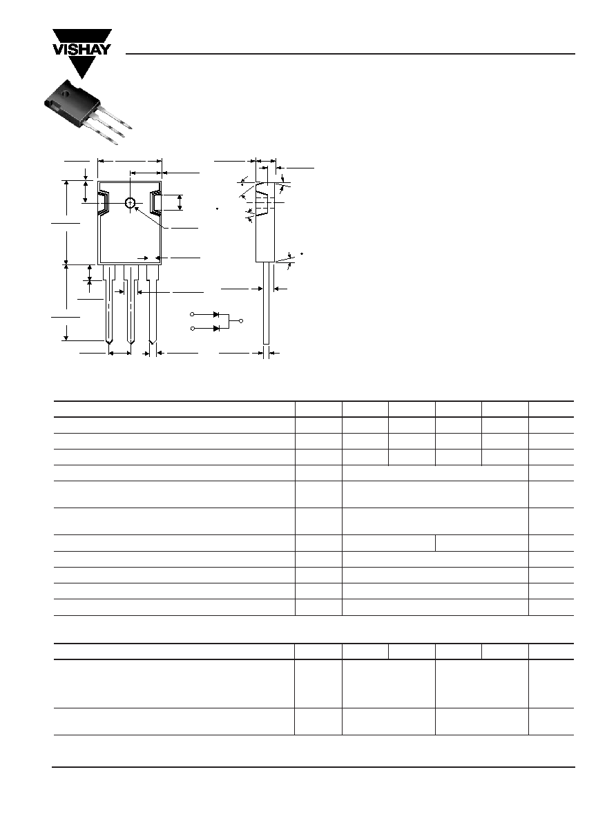
PIN 1
PIN 3
CASE
0.245 (6.2)
0.225 (5.7)
0.645 (16.4)
0.625 (15.9)
0.323 (8.2)
0.313 (7.9)
0.142 (3.6)
0.138 (3.5)
0.170
(4.3)
0.086 (2.18)
0.076 (1.93)
0.160 (4.1)
0.140 (3.5)
0.225 (5.7)
0.205 (5.2)
0.127 (3.22)
0.117 (2.97)
0.048 (1.22)
0.044 (1.12)
0.795 (20.2)
0.775 (19.6)
0.840 (21.3)
0.820 (20.8)
1
2
3
0.078 REF
(1.98)
0.203 (5.16)
0.193 (4.90)
10 TYP.
BOTH SIDES
30
10
°
1 REF.
0.118 (3.0)
0.108 (2.7)
0.030 (0.76)
0.020 (0.51)
BOTH
SIDES
PIN 2
TO-247AD (TO-3P)
Dimensions
in inches and
(millimeters)
相關(guān)PDF資料 |
PDF描述 |
|---|---|
| MBR3035WT | 15 A, 35 V, SILICON, RECTIFIER DIODE, TO-247AC |
| MBR3040-BP | 30 A, 40 V, SILICON, RECTIFIER DIODE, TO-3 |
| MBR3060-BP | 30 A, 60 V, SILICON, RECTIFIER DIODE, TO-3 |
| MBR3030-BP | 30 A, 30 V, SILICON, RECTIFIER DIODE, TO-3 |
| MBR3040PT | 30 A, 40 V, SILICON, RECTIFIER DIODE |
相關(guān)代理商/技術(shù)參數(shù) |
參數(shù)描述 |
|---|---|
| MBR3060PT _T0 _10001 | 制造商:PanJit Touch Screens 功能描述: |
| MBR3060PT C0 | 制造商:SKMI/Taiwan 功能描述:Diode Schottky 60V 30A 3-Pin(3+Tab) TO-3P Tube 制造商:Taiwan Semiconductor 功能描述:Diode Schottky 60V 30A 3-Pin(3+Tab) TO-3P Tube |
| MBR3060PT | 制造商:Fairchild Semiconductor Corporation 功能描述:Diode |
| MBR3060PT/45 | 功能描述:肖特基二極管與整流器 30 Amp 60 Volt RoHS:否 制造商:Skyworks Solutions, Inc. 產(chǎn)品:Schottky Diodes 峰值反向電壓:2 V 正向連續(xù)電流:50 mA 最大浪涌電流: 配置:Crossover Quad 恢復(fù)時(shí)間: 正向電壓下降:370 mV 最大反向漏泄電流: 最大功率耗散:75 mW 工作溫度范圍:- 65 C to + 150 C 安裝風(fēng)格:SMD/SMT 封裝 / 箱體:SOT-143 封裝:Reel |
| MBR3060PT_B0_10001#DELETED BY PJT# | 制造商:PanJit Touch Screens 功能描述: |
發(fā)布緊急采購(gòu),3分鐘左右您將得到回復(fù)。