- 您現(xiàn)在的位置:買賣IC網(wǎng) > PDF目錄384706 > MAX836-MAX837 (Maxim Integrated Products, Inc.) 4-Pin Micropower Voltage Monitors PDF資料下載
參數(shù)資料
| 型號: | MAX836-MAX837 |
| 廠商: | Maxim Integrated Products, Inc. |
| 英文描述: | 4-Pin Micropower Voltage Monitors |
| 中文描述: | 4引腳微功耗電壓監(jiān)視器 |
| 文件頁數(shù): | 2/6頁 |
| 文件大小: | 61K |
| 代理商: | MAX836-MAX837 |
M
4-Pin Mic ropower Voltage Monitors
2
_______________________________________________________________________________________
ABSOLUTE MAXIMUM RATINGS
V
CC
, OUT to GND (MAX836)....................................-0.3V to 12V
IN, OUT to GND (MAX837).........................-0.3V to (V
CC
+ 0.3V)
Input Current
V
CC
.................................................................................20mA
IN.....................................................................................10mA
Output Current, OUT...........................................................20mA
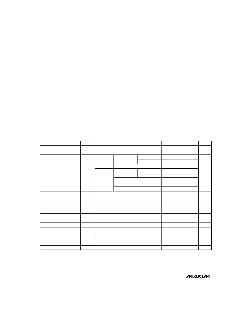
ELECTRICAL CHARACTERISTICS
(V
CC
= +2.5V to +11.0V, T
A
= T
MIN
to T
MAX
, unless otherwise noted. Typical values are at T
A
= +25°C.)
Stresses beyond those listed under “Absolute Maximum Ratings” may cause permanent damage to the device. These are stress ratings only, and functional
operation of the device at these or any other conditions beyond those indicated in the operational sections of the specifications is not implied. Exposure to
absolute maximum rating conditions for extended periods may affect device reliability.
Rate of Rise, V
CC
............................................................100V/μs
Continuous Power Dissipation
SOT143 (derate 4mW/°C above +70°C)......................320mW
Operating Temperature Range ...........................-40°C to +85°C
Storage Temperature Range.............................-65°C to +150°C
Lead Temperature (soldering, 10sec) .............................+300°C
V
0.4
V
OL
Output Voltage Low
V
V
CC
- 0.5
V
OH
Output Voltage High
μA
±1
I
LOUT
Output Leakage Current
(Note 4)
ns
680
t
FT
OUT Fall Time
ns
260
t
RT
OUT Rise Time
μs
35
Glitch Immunity
μs
80
t
PL
Propagation Delay
V
2.5
11
V
CC
Operating Voltage Range
(Note 1)
±3
±12
nA
I
IN
IN Leakage Current (Note 3)
V
V
CC
- 1
V
IN
IN Operating Voltage Range
(Note 1)
mV
6
V
HYST
Trip Threshold Voltage
Hysteresis
V
1.185
1.169
1.204
1.204
1.215
1.231
V
TH
Trip Threshold Voltage
UNITS
MIN
TYP
MAX
SYMBOL
PARAMETER
V
CC
= 3.6V
10
15
5.0
8.0
13
V
IN
falling
T
A
= T
MIN
to T
MAX
V
IN
< V
THMIN,
I
SINK
= 500μA
V
IN
> V
THMAX
, I
SOURCE
= 500μA (MAX837 only)
V
IN
> V
THMAX
(MAX836 only)
V
IN
= V
TH
V
CC
= 5.0V, 50mV overdrive
V
CC
= 5.0V, no load (MAX836 pull-up = 10k
)
V
CC
= 5.0V, no load (MAX837 only)
V
CC
= 5V, IN = low to high
V
CC
= 5.0V, 100mV overdrive
T
A
= +25°C
T
A
= 0°C to +70°C
CONDITIONS
T
A
= +25°C
μ
A
3.5
6.5
Supply Current (Note 2)
V
IN
= 1.16V,
OUT = low
I
CC
V
CC
= full operating range
2.0
T
A
= +25°C
T
A
= T
MIN
to T
MAX
V
CC
= 3.6V
V
IN
= 1.25V,
OUT = high
V
CC
= full operating range
Note 1:
The voltage-detector output remains in the direct state for V
CC
down to 1.2V when V
IN
≤
V
CC
/ 2.
Note 2:
Supply current has a monotonic dependence on V
CC
(see Typical Operating Characteristics).
Note 3:
IN leakage current has a monotonic dependence on V
CC
(see Typical Operating Characteristics).
Note 4:
The MAX836 open-drain output can be pulled up to a voltage greater than V
CC
, but may not exceed 11V.
相關(guān)PDF資料 |
PDF描述 |
|---|---|
| MAX836 | 4-Pin Micropower Voltage Monitors |
| MAX837EUS-T | 4-Pin Micropower Voltage Monitors |
| MAX837EUS | PLASTIC ENCAPSULATED DEVICES |
| MAX8506ETE | PWM Step-Down DC-DC Converters with 75m? Bypass FET for WCDMA and cdmaOne Handsets |
| MAX8507ETE | Quadruple 2-Input Positive-AND Gates 14-CDIP -55 to 125 |
相關(guān)代理商/技術(shù)參數(shù) |
參數(shù)描述 |
|---|---|
| MAX8375 | 制造商:PCTEL 功能描述:ANTENNA UNIT |
| MAX8375-NL | 制造商:PCTEL 功能描述:ANTENNA UNIT |
| MAX8375S | 制造商:PCTEL 功能描述:ANTENNA UNIT |
| MAX837EUS | 制造商:Maxim Integrated Products 功能描述:4-PIN MICROPOWER VOLTAGE MONITORS - Rail/Tube |
| MAX837EUS+ | 制造商:Maxim Integrated Products 功能描述:VOLT SUPERVISOR MONITOR 1.204V 4PIN SOT-143 - Rail/Tube 制造商:Maxim Integrated Products 功能描述:Volt Supervisor Monitor 4-Pin (3+Tab) SOT-143 |
發(fā)布緊急采購,3分鐘左右您將得到回復(fù)。