- 您現(xiàn)在的位置:買賣IC網(wǎng) > PDF目錄383480 > MAX6627MKA-T (MAXIM INTEGRATED PRODUCTS INC) Remote 【1∑C Accurate Digital Temperature Sensors with SPI-Compatible Serial Interface PDF資料下載
參數(shù)資料
| 型號(hào): | MAX6627MKA-T |
| 廠商: | MAXIM INTEGRATED PRODUCTS INC |
| 元件分類: | 溫度/濕度傳感器 |
| 英文描述: | Remote 【1∑C Accurate Digital Temperature Sensors with SPI-Compatible Serial Interface |
| 中文描述: | DIGITAL TEMP SENSOR-SERIAL, 12BIT(s), 5.50Cel, RECTANGULAR, SURFACE MOUNT |
| 封裝: | MO-178, SOT-23, 8 PIN |
| 文件頁數(shù): | 7/9頁 |
| 文件大小: | 151K |
| 代理商: | MAX6627MKA-T |
Filter high-frequency electromagnetic interference
(EMI) at DXP and DXN with an external 2200pF capaci-
tor connected between the two inputs. This capacitor
can be increased to about 3300pF (max), including
cable capacitance. A capacitance higher than 3300pF
introduces errors due to the rise time of the switched-
current source.
PC Board Layout
1) Place the MAX6627/MAX6628 as close as practical
to the remote diode. In a noisy environment, such
as a computer motherboard, this distance can be
4in to 8in, or more, as long as the worst noise
sources (such as CRTs, clock generators, memory
buses, and ISA/PCI buses) are avoided.
2) Do not route the DXP/DXN lines next to the deflec-
tion coils of a CRT. Also, do not route the traces
across a fast memory bus, which can easily intro-
duce +30
°
C error, even with good filtering.
Otherwise, most noise sources are fairly benign.
3) Route the DXP and DXN traces parallel and close to
each other, away from any high-voltage traces such
as +12VDC. Avoid leakage currents from PC board
contamination. A 20M
leakage path from DXP to
ground causes approximately +1
°
C error.
4) Connect guard traces to GND on either side of the
DXP/DXN traces (Figure 3). With guard traces in
place, routing near high-voltage traces is no longer
an issue.
5) Route as few vias and crossunders as possible to
minimize copper/solder thermocouple effects.
6) When introducing a thermocouple, make sure that
both the DXP and the DXN paths have matching
thermocouples. In general, PC board-induced ther-
mocouples are not a serious problem. A copper
solder thermocouple exhibits 3μV/
°
C, and it takes
approximately 200μV of voltage error at DXP/DXN
to cause a +1
°
C measurement error, so most para-
sitic thermocouple errors are swamped out.
7) Use wide traces. Narrow traces are more inductive
and tend to pick up radiated noise. The 10mil
widths and spacings recommended in Figure 3 are
not absolutely necessary (as they offer only a minor
improvement in leakage and noise), but use them
where practical.
8) Placing an electrically clean copper ground plane
between the DXP/DXN traces and traces carrying
high-frequency noise signals helps reduce EMI.
Twisted Pair and Shielded Cables
For remote-sensor distances longer than 8in, or in par-
ticularly noisy environments, a twisted pair is recom-
mended. Its practical length is 6ft to 12ft (typ) before
noise becomes a problem, as tested in a noisy elec-
tronics laboratory. For longer distances, the best solu-
tion is a shielded twisted pair like that used for audio
microphones. For example, Belden #8451 works well
for distances up to 100ft in a noisy environment.
Connect the twisted pair to DXP and DXN and the
shield to ground, and leave the shield
’
s remote end
unterminated. Excess capacitance at DXN or DXP limits
practical remote-sensor distances (see
Typical
Operating Characteristics
).
For very long cable runs, the cable
’
s parasitic capaci-
tance often provides noise filtering, so the recommend-
ed 2200pF capacitor can often be removed or reduced
in value. Cable resistance also affects remote-sensor
accuracy. A 1
series resistance introduces about
+1/2
°
C error.
M
Remote ±1°C Accurate Digital Temperature
Sensors with SPI-Compatible Serial Interface
_______________________________________________________________________________________
7
MINIMUM
10mils
10mils
10mils
10mils
GND
DXN
DXP
GND
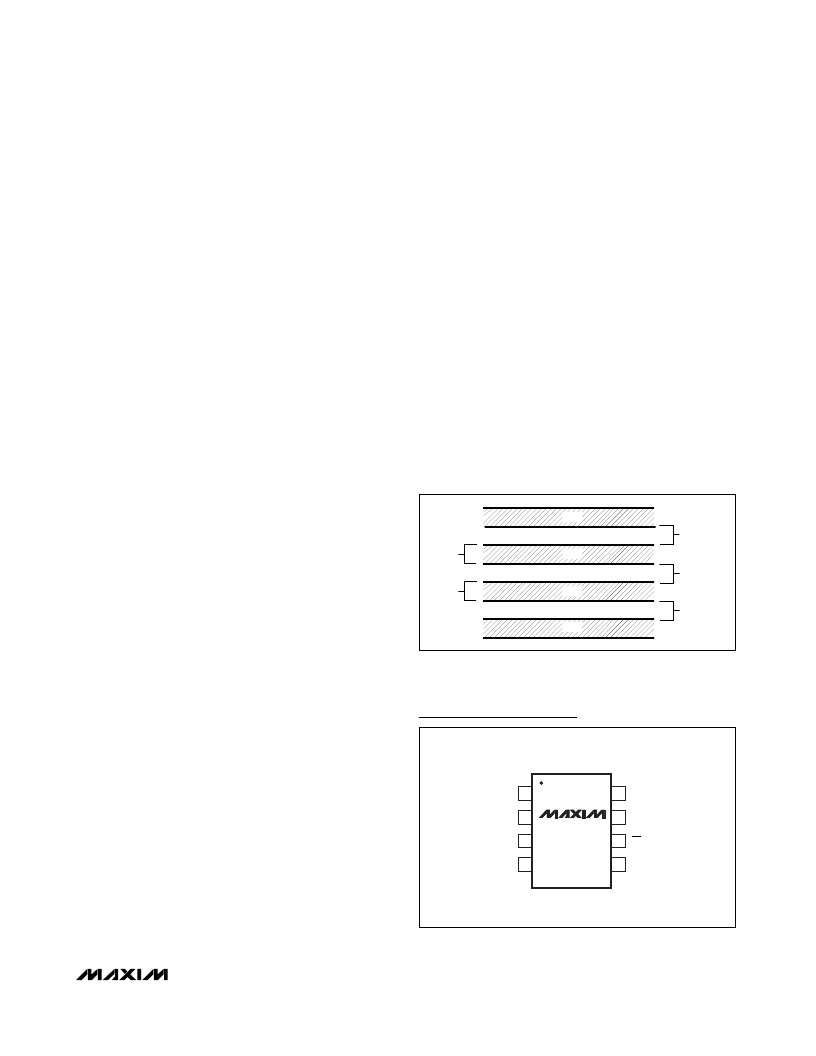
Figure 3. Recommended DXP/DXN PC Traces
SCK
V
CC
1
2
8
7
N.C.
SO
DXN
DXP
GND
SOT23
TOP VIEW
3
4
6
5
MAX6627
MAX6628
CS
Pin Configuration
相關(guān)PDF資料 |
PDF描述 |
|---|---|
| MAX6628MKA-T | Remote 【1∑C Accurate Digital Temperature Sensors with SPI-Compatible Serial Interface |
| MAX6627 | Quadruple 2-Input Exclusive-OR Gates 14-CFP -55 to 125 |
| MAX6630MUT-T | 12-Bit Sign Digital Temperature Sensors with Serial Interface |
| MAX6630 | Decade Counter 14-CDIP -55 to 125 |
| MAX6631 | Decade Counter 14-CDIP -55 to 125 |
相關(guān)代理商/技術(shù)參數(shù) |
參數(shù)描述 |
|---|---|
| MAX6627MTA+ | 制造商:Maxim Integrated Products 功能描述:REMOTE ?1?C ACCURATE DIGITAL TEMPERATURE SENSORS WITH SPI - Rail/Tube |
| MAX6627MTA+T | 功能描述:板上安裝溫度傳感器 1C Accurate Temperature Sensor RoHS:否 制造商:Omron Electronics 輸出類型:Digital 配置: 準(zhǔn)確性:+/- 1.5 C, +/- 3 C 溫度閾值: 數(shù)字輸出 - 總線接口:2-Wire, I2C, SMBus 電源電壓-最大:5.5 V 電源電壓-最小:4.5 V 最大工作溫度:+ 50 C 最小工作溫度:0 C 關(guān)閉: 安裝風(fēng)格: 封裝 / 箱體: 設(shè)備功能:Temperature and Humidity Sensor |
| MAX6628MKA | 制造商:Maxim Integrated Products 功能描述:REMOTE +/- 1-DEGREE C ACCURATE DIGITAL TEMPER - Bulk |
| MAX6628MKA+ | 制造商:Maxim Integrated Products 功能描述:TEMP SENSOR DGTL 3-WIRE/SPI 8PIN SOT-23 - Rail/Tube |
| MAX6628MKA+T | 制造商:Maxim Integrated Products 功能描述:TEMP SENSOR DGTL 3-WIRE/SPI 8PIN SOT-23 - Tape and Reel |
發(fā)布緊急采購,3分鐘左右您將得到回復(fù)。