Hysteresis
Hysteresis adds noise immunity to the voltage monitors
and prevents oscillation due to repeated triggering
when V
IN
is near the threshold trip voltage. The hystere-
sis in a comparator creates two trip points: one for the
rising input voltage (V
TH
+) and one for the falling input
voltage (V
TH
-). These thresholds are shown in Figure 6.
The internal hysteresis options of the MAX6457/
MAX6458/MAX6459 are designed to eliminate the need
for adding an external hysteresis circuit.
Timeout Period
The timeout period (t
TP
) for the MAX6457 is the time
from when the input (IN+) crosses the rising input
threshold (V
TH
+) to when the output goes high (see
Figures 6 and 7). For the MAX6458, the monitored volt-
age must be in the
“
window
”
before the timeout starts.
The MAX6459 and MAX6460 do not offer the extended
timeout option (150ms). The extended timeout period is
suitable for overvoltage protection applications requir-
ing transient immunity to avoid false output assertion
due to noise spikes.
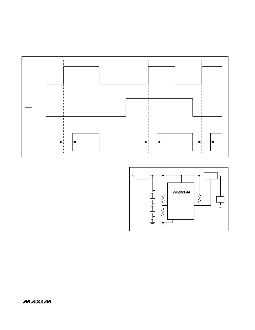
Latched-Output Operation
The MAX6457 features a digital latch input (
CLEAR
) to
latch any overvoltage event. If the voltage on IN+ (V
IN
+)
is below the internal threshold (V
TH
-), or if V
CC
is below
4V, OUT remains low regardless of the state of
CLEAR
.
Drive
CLEAR
high to latch OUT high when V
IN
+ exceeds
V
TH
+. When
CLEAR
is high, OUT does not deassert if
V
IN
+ drops back below V
IN
-. Toggle
CLEAR
to deassert
OUT. Drive
CLEAR
low to make the latch transparent
(Figure 7).
CLEAR
must be low when powering up the
MAX6457. To initiate self-clear at power-up, add a 100k
pullup resistor from
CLEAR
to V
CC
and a 1μF capacitor
from
CLEAR
to GND to hold
CLEAR
low. Connect
CLEAR
to GND when not used. See Figure 9.
M
High-Voltage, Low-Current Voltage Monitors in
SOT Packages
_______________________________________________________________________________________
9
IN+
OUT
>V
TH+
<V
TH-
V
CC
V
CC
0
0
t
TP
t
TP
t
TP
CLEAR
Figure 7. Timing Diagram (MAX6457)
5-CELL
Li+
BATTERY
STACK
BATTERY
CHARGER
DC-DC
CONVERTER
LOAD
R1
R2
R
PULLUP
IN
OUT
+21V
V
CC
GND
IN+
OUT
(OUTA FOR
MAX6459)
MAX6457
–
MAX6460
SHDN
Figure 8. Undervoltage Lockout Typical Application Circuit
