- 您現(xiàn)在的位置:買賣IC網(wǎng) > PDF目錄296465 > MAX6331TUR-T (MAXIM INTEGRATED PRODUCTS INC) VOLT REGULATOR|FIXED|+3.3V|TO-236|3PIN|PLASTIC PDF資料下載
參數(shù)資料
| 型號: | MAX6331TUR-T |
| 廠商: | MAXIM INTEGRATED PRODUCTS INC |
| 元件分類: | 電源管理 |
| 英文描述: | VOLT REGULATOR|FIXED|+3.3V|TO-236|3PIN|PLASTIC |
| 中文描述: | 1-CHANNEL POWER SUPPLY SUPPORT CKT, PDSO3 |
| 封裝: | SOT-23, 3 PIN |
| 文件頁數(shù): | 6/8頁 |
| 文件大?。?/td> | 223K |
| 代理商: | MAX6331TUR-T |
MAX6330/MAX6331
Precision Shunt Regulators with Reset
in SOT23-3
6
_______________________________________________________________________________________
resistor used. Ensure that the resistor’s power rating is
adequate, using the following general power equation:
PR = IIN(VIN(max) - VSHUNT)
= I2INRS
= (VIN(max) - VSHUNT)
2 / RS
_____________Applications Information
Negative-Going VSHUNT Transients
In addition to issuing a reset to the P during power-up,
power-down, and brownout conditions, the MAX6330/
MAX6331 are relatively immune to short-duration nega-
tive-going VSHUNT transients (glitches). Additional
bypass filter capacitance mounted close to the SHUNT
pin provides additional transient immunity.
Choosing the Bypass Capacitor, CL
The bypass capacitor (CL) on the SHUNT pin can sig-
nificantly affect the device’s load-transient response, so
choose it carefully. When a load transient occurs, the
current for this load is diverted from the shunt regulator.
The maximum load current that can be diverted from
the regulator is:
ILOAD (diverted from regulator)
= ISHUNT(max) - ISHUNT(min)
= 50mA - 100A
= 49.9mA
The shunt regulator has a finite response to this tran-
sient. The instantaneous requirements of the load
change are met by the charge on CL, resulting in over-
shoot/undershoot on VSHUNT. The magnitude of this
overshoot/undershoot increases with ISHUNT and
decreases with CL. When VSHUNT undershoots, the
shunt current decreases to where it will only draw qui-
escent current (IQ), and the shunt element turns off. At
this point, VSHUNT will slew toward VIN at the following
rate:
VSHUNT / t = (IIN - ILOAD - 60A) / CL
As VSHUNT rises, it will turn on the shunt regulator when
it can sink 100A of current. A finite response time for
the shunt regulator to start up will result in a brief over-
shoot of VSHUNT before it settles into its regulation volt-
age. Therefore, ILOAD should always be 100A or more
below IIN, or VSHUNT will not recover to its regulation
point. To prevent this condition, be sure to select the
correct series-resistor RS value (see the Shunt
Regulator section).
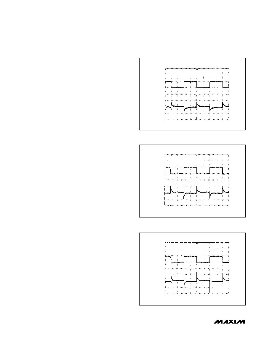
Figures 2, 3, and 4 show load-transient responses for
different choices of bypass capacitors on VSHUNT.
These photos clearly illustrate the benefits and draw-
backs of the capacitor options. A smaller bypass
ILOAD
2mA/div
VSHUNT
20mV/div
0
MAX6330
FIG
02
IIN = 2mA, ILOAD = 0 to 1.9mA
VSHUNT IS AC COUPLED
Figure 2. Load-Transient Response with CL = 0.22F
ILOAD
2mA/div
VSHUNT
20mV/div
0
MAX6330
FIG
03
IIN = 2mA, ILOAD = 0 to 1.9mA,
VSHUNT IS AC COUPLED
Figure 3. Load-Transient Response with CL = 0.033F
ILOAD
2mA/div
VSHUNT
20mV/div
0
MAX6330
FIG
04
IIN = 2mA, ILOAD = 0 to 1.9mA
VSHUNT IS AC COUPLED
Figure 4. Load-Transient Response with CL = 0.0047F
相關(guān)PDF資料 |
PDF描述 |
|---|---|
| MAX6330LUR-T | VOLT REGULATOR|FIXED|+5V|TO-236|3PIN|PLASTIC |
| MAX6332UR16D1-T | Voltage Detector |
| MAX6332UR16D2-T | Voltage Detector |
| MAX6332UR17D3-T | Voltage Detector |
| MAX6332UR18D1-T | Voltage Detector |
相關(guān)代理商/技術(shù)參數(shù) |
參數(shù)描述 |
|---|---|
| MAX6332_V3 | 制造商:MAXIM 制造商全稱:Maxim Integrated Products 功能描述:3-Pin, Ultra-Low-Voltage, Low-Power ??P Reset Circuits |
| MAX6332UR | 制造商:MAXIM 制造商全稱:Maxim Integrated Products 功能描述:3-Pin, Ultra-Low-Voltage, Low-Power uP Reset Circuits |
| MAX6332UR16D1 | 制造商:Maxim Integrated Products 功能描述:3-PIN ULTRA-LOW-VOLTAGE LOW-POWER - Rail/Tube |
| MAX6332UR16D1+ | 制造商:Maxim Integrated Products 功能描述:PROCESSOR SUPERVISOR 1.6V 3.3UA 3PIN SOT-23 - Rail/Tube |
| MAX6332UR16D1+T | 功能描述:監(jiān)控電路 3-Pin uPower Reset Circuit RoHS:否 制造商:STMicroelectronics 監(jiān)測電壓數(shù): 監(jiān)測電壓: 欠電壓閾值: 過電壓閾值: 輸出類型:Active Low, Open Drain 人工復(fù)位:Resettable 監(jiān)視器:No Watchdog 電池備用開關(guān):No Backup 上電復(fù)位延遲(典型值):10 s 電源電壓-最大:5.5 V 最大工作溫度:+ 85 C 安裝風(fēng)格:SMD/SMT 封裝 / 箱體:UDFN-6 封裝:Reel |
發(fā)布緊急采購,3分鐘左右您將得到回復(fù)。