- 您現(xiàn)在的位置:買賣IC網 > PDF目錄383403 > MAX4507EWN (MAXIM INTEGRATED PRODUCTS INC) Fault-Protected, High-Voltage Signal-Line Protectors PDF資料下載
參數(shù)資料
| 型號: | MAX4507EWN |
| 廠商: | MAXIM INTEGRATED PRODUCTS INC |
| 元件分類: | 運動控制電子 |
| 英文描述: | Fault-Protected, High-Voltage Signal-Line Protectors |
| 中文描述: | OCTAL 1-CHANNEL, SGL POLE SGL THROW SWITCH, PDSO18 |
| 封裝: | SOP-18 |
| 文件頁數(shù): | 2/12頁 |
| 文件大?。?/td> | 393K |
| 代理商: | MAX4507EWN |
M
Fault-Protected, High-Voltage
Signal-Line Protectors
2
_______________________________________________________________________________________
ABSOLUTE MAXIMUM RATINGS
(Voltages Referenced to GND)
V+........................................................................-0.3V to +44.0V
V-.........................................................................-44.0V to +0.3V
V+ to V-................................................................-0.3V to +44.0V
IN_ or OUT_.........................................................................±44V
IN_ Overvoltage with Power On...........................................±36V
IN_ Overvoltage with Power Off...........................................±40V
Continuous Current into Any Terminal..............................±30mA
Peak Current into Any Terminal
(pulsed at 1ms, 10% duty cycle).................................±70mA
Continuous Power Dissipation (T
A
= +70°C)
8-Pin Narrow SO (derate 5.88mW/°C above +70°C) ....471mW
8-Pin Plastic DIP (derate 9.09mW/°C above +70°C).....727mW
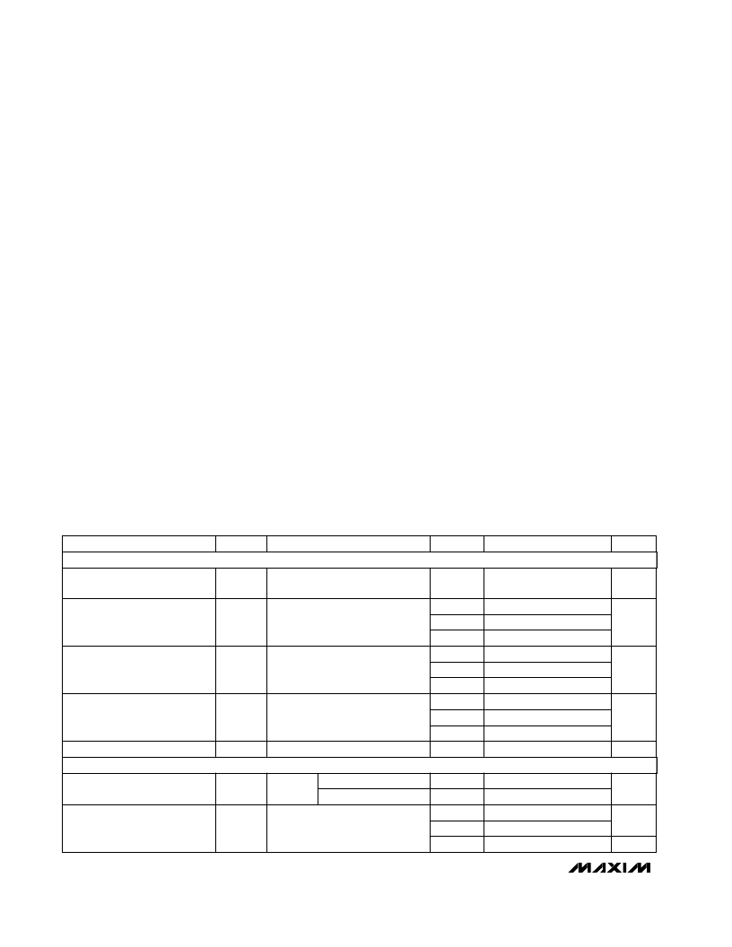
ELECTRICAL CHARACTERISTICS
(V+ = +15V, V- = -15V, T
A
= T
MIN
to T
MAX
, unless otherwise noted. Typical values are at T
A
= +25°C.) (Note 3)
SYMBOL
PARAMETER
ANALOG SWITCH
Stresses beyond those listed under “Absolute Maximum Ratings” may cause permanent damage to the device. These are stress ratings only, and functional
operation of the device at these or any other conditions beyond those indicated in the operational sections of the specifications is not implied. Exposure to
absolute maximum rating conditions for extended periods may affect device reliability.
8-Pin CERDIP (derate 8.00mW/°C above +70°C) ...........640mW
18-Pin Wide SO (derate 9.52mW/ °C above +70°C).......762mW
18-Pin Plastic DIP (derate 11.11mW/ °C above +70°C)...889mW
18-Pin CERDIP (derate 10.53mW/ °C above +70°C) ......842mW
20-Pin SSOP (derate 11.11mW/°C above +70°C)...........640mW
Operating Temperature Ranges
MAX4506C_A /MAX4607C_ _.............................0°C to +70°C
MAX4506E_A/MAX4607E_ _ ...........................-40°C to +85°C
MAX4506MJA/MAX4607MJN........................-55°C to +125°C
Storage Temperature Range.............................-65°C to +160°C
Lead Temperature (soldering, 10sec).............................+300°C
RECOMMENDED OPERATING GUIDELINES
V+ to GND..............................................................-0.3V to +40V
V- to GND...............................................................-32V to +0.3V
V+ to V- ..................................................................................40V
IN_........................................................................................±40V
OUT_ ...............................................................................V+ to V-
Note 1:
OUT_ pins are not fault protected. Signals on OUT_ exceeding V+ or V- are clamped by internal diodes. Limit forward-diode
current to maximum current rating.
Note 2:
IN_ pins are fault protected. Signals on IN_ exceeding -36V to +36V may damage the device. These limits apply with power
applied to V+ or V-, or ±40V with V+ = V- = 0.
IN_ to OUT_..........................................................40V Differential
Continuous Current into Any Terminal..............................
≤
30mA
Peak Current into Any Terminal
(pulsed at 1ms, 10% duty cycle).................................
≤
70mA
C
IN
Input Capacitance
FAULT PROTECTION
pF
20
V
IN
= 0, f = 1MHz
+25°C
V
IN_
Fault-Protected Analog Signal
Range
V
-36
-40
36
40
(Notes
2, 3)
C, E, M
C, E, M
+25°C
Applies with power on
Applies with power off
-20
-200
-10
0.1
20
200
10
nA
C, E
M
V
IN_
= ±25V, V
OUT_
= open
I
IN_
Input Signal-Path Leakage
Current, Supplies On
65
100
125
150
7
10
R
ON
V
V-
V+
V
IN_
Fault-Free Analog Signal Range
(Note 4)
-400
400
I
OUT_ON
Signal-Path Leakage Current
(Note 7)
μA
-20
20
nA
-
0.5
0.5
12
Analog Signal-Path Resistance
1
R
ON
Signal-Path Resistance Match
(Note 6)
UNITS
MIN
TYP
MAX
V+ = +15V, V- = -15V,
V
IN_
= ±15V
V
OUT_
= ±10V, V
IN_
= ±10V or
floating
V
IN_
= ±10V, I
OUT_
= 1mA
V
IN_
= V
OUT_
= ±10V, I
OUT
= 1mA
CONDITIONS
+25°C
C, E
M
+25°C
C, E
C, E, M
M
C, E
+25°C
M
T
A
相關PDF資料 |
PDF描述 |
|---|---|
| MAX4506 | Fault-Protected, High-Voltage Signal-Line Protectors |
| MAX4506CPA | Fault-Protected, High-Voltage Signal-Line Protectors |
| MAX4506CSA | Fault-Protected, High-Voltage Signal-Line Protectors |
| MAX4506EPA | Replaced by TMS320VC5510 : Digital Signal Processor 144-LQFP |
| MAX4506ESA | Fault-Protected, High-Voltage Signal-Line Protectors |
相關代理商/技術參數(shù) |
參數(shù)描述 |
|---|---|
| MAX4507EWN+ | 功能描述:模擬開關 IC RoHS:否 制造商:Texas Instruments 開關數(shù)量:2 開關配置:SPDT 開啟電阻(最大值):0.1 Ohms 切換電壓(最大): 開啟時間(最大值): 關閉時間(最大值): 工作電源電壓:2.7 V to 4.5 V 最大工作溫度:+ 85 C 安裝風格:SMD/SMT 封裝 / 箱體:DSBGA-16 |
| MAX4507EWN+T | 功能描述:模擬開關 IC RoHS:否 制造商:Texas Instruments 開關數(shù)量:2 開關配置:SPDT 開啟電阻(最大值):0.1 Ohms 切換電壓(最大): 開啟時間(最大值): 關閉時間(最大值): 工作電源電壓:2.7 V to 4.5 V 最大工作溫度:+ 85 C 安裝風格:SMD/SMT 封裝 / 箱體:DSBGA-16 |
| MAX4507EWN-T | 功能描述:模擬開關 IC RoHS:否 制造商:Texas Instruments 開關數(shù)量:2 開關配置:SPDT 開啟電阻(最大值):0.1 Ohms 切換電壓(最大): 開啟時間(最大值): 關閉時間(最大值): 工作電源電壓:2.7 V to 4.5 V 最大工作溫度:+ 85 C 安裝風格:SMD/SMT 封裝 / 箱體:DSBGA-16 |
| MAX4507MJN | 功能描述:模擬開關 IC RoHS:否 制造商:Texas Instruments 開關數(shù)量:2 開關配置:SPDT 開啟電阻(最大值):0.1 Ohms 切換電壓(最大): 開啟時間(最大值): 關閉時間(最大值): 工作電源電壓:2.7 V to 4.5 V 最大工作溫度:+ 85 C 安裝風格:SMD/SMT 封裝 / 箱體:DSBGA-16 |
| MAX4508C/D | 功能描述:多路器開關 IC RoHS:否 制造商:Texas Instruments 通道數(shù)量:1 開關數(shù)量:4 開啟電阻(最大值):7 Ohms 開啟時間(最大值): 關閉時間(最大值): 傳播延遲時間:0.25 ns 工作電源電壓:2.3 V to 3.6 V 工作電源電流: 最大工作溫度:+ 85 C 安裝風格:SMD/SMT 封裝 / 箱體:UQFN-16 |
發(fā)布緊急采購,3分鐘左右您將得到回復。