- 您現(xiàn)在的位置:買賣IC網(wǎng) > PDF目錄383367 > MAX3460EPD (MAXIM INTEGRATED PRODUCTS INC) +5V, Fail-Safe, 20Mbps, Profibus RS-485/ RS-422 Transceivers PDF資料下載
參數(shù)資料
| 型號(hào): | MAX3460EPD |
| 廠商: | MAXIM INTEGRATED PRODUCTS INC |
| 元件分類: | 通用總線功能 |
| 英文描述: | +5V, Fail-Safe, 20Mbps, Profibus RS-485/ RS-422 Transceivers |
| 中文描述: | LINE TRANSCEIVER, PDIP14 |
| 封裝: | 0.300 INCH, PLASTIC, MS-058AC, DIP-14 |
| 文件頁(yè)數(shù): | 11/14頁(yè) |
| 文件大小: | 376K |
| 代理商: | MAX3460EPD |
第1頁(yè)第2頁(yè)第3頁(yè)第4頁(yè)第5頁(yè)第6頁(yè)第7頁(yè)第8頁(yè)第9頁(yè)第10頁(yè)當(dāng)前第11頁(yè)第12頁(yè)第13頁(yè)第14頁(yè)
M
+5V, Fail-Safe, 20Mbps, Profibus RS-485/
RS-422 Transceivers
______________________________________________________________________________________
11
Applications Information
128 Transceivers on the Bus
The standard RS-485 receiver input impedance is 12k
(one-unit load), and the standard driver can drive up to
32 unit loads. The MAX3460
–
MAX3464 family of trans-
ceivers has a 1/4-unit-load receiver input impedance
(48k
), allowing up to 128 transceivers to be connect-
ed in parallel on one communication line. Any combina-
tion of these devices and/or other RS-485 transceivers
with a total of 32 unit loads or less can be connected to
the line.
Low-Power Shutdown Mode
(except MAX3462)
Low-power shutdown mode is initiated by bringing
SHDN high (MAX3460/MAX3461), or both
RE
high and
DE low. In shutdown, the devices typically draw only
1μA of supply current.
RE
and DE can be driven simul-
taneously; the parts are guaranteed not to enter shut-
down if
RE
is high and DE is low for less than 50ns. If
the inputs are in this state for at least 800ns, the parts
are guaranteed to enter shutdown.
Driver Output Protection
Two mechanisms prevent excessive output current and
power dissipation caused by faults or by bus con-
tention. The first, a foldback current limit on the output
stage, provides immediate protection against short cir-
cuits over the whole common-mode voltage range (see
Typical Operating Characteristics
). The second, a ther-
mal shutdown circuit, forces the driver outputs into a
high-impedance state if the die temperature exceeds
+140
°
C.
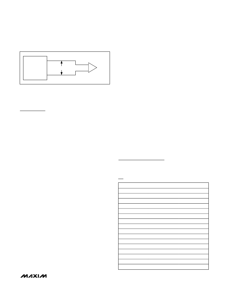
Propagation Delay
Many digital encoding schemes depend on the difference
between the driver and receiver propagation delay times.
Typical propagation delays are shown in the
Typical
Operating Characteristics
. The difference in receiver delay
times, |t
PLH
- t
PHL
|, is a maximum of 2ns. The driver skew
time |t
PLH
- t
PHL
| is also a maximum of 2ns.
Typical Applications
The MAX3460
–
MAX3464 transceivers are designed for
bidirectional data communications on multipoint bus
transmission lines. Figures 13 and 14 show typical net-
work applications circuits. To minimize reflections, the
line should be terminated at both ends in its character-
istic impedance, and stub lengths off the main line
should be kept as short as possible.
Profibus Termination
The MAX3460
–
MAX3464 are designed for driving
Profibus termination networks. With a worst-case load-
ing of two termination networks with 220
termination
impedance and 390
pullups and pulldowns, the dri-
vers can drive V
A-B
> 2.1V output.
Chip Information
TRANSISTOR COUNT: 610
PROCESS: BiCMOS
V
ID
ATE
RECEIVER
OUTPUT
B
A
R
Figure 12. Receiver Propagation Delay Test Circuit
Ordering Information (continued)
PART
TEMP RANGE
0
°
C to +70
°
C
0
°
C to +70
°
C
-40
°
C to +85
°
C
-40
°
C to +85
°
C
0
°
C to +70
°
C
0
°
C to +70
°
C
-40
°
C to +85
°
C
-40
°
C to +85
°
C
0
°
C to +70
°
C
0
°
C to +70
°
C
-40
°
C to +85
°
C
-40
°
C to +85
°
C
0
°
C to +70
°
C
0
°
C to +70
°
C
-40
°
C to +85
°
C
-40
°
C to +85
°
C
PIN-PACKAGE
14 SO
14 Plastic DIP
14 SO
14 Plastic DIP
8 SO
8 Plastic DIP
8 SO
8 Plastic DIP
8 SO
8 Plastic DIP
8 SO
8 Plastic DIP
8 SO
8 Plastic DIP
8 SO
8 Plastic DIP
MAX3461
CSD
MAX3461CPD
MAX3461ESD
MAX3461EPD
MAX3462
CSA
MAX3462CPA
MAX3462ESA
MAX3462EPA
MAX3463
CSA
MAX3463CPA
MAX3463ESA
MAX3463EPA
MAX3464
CSA
MAX3464CPA
MAX3464ESA
MAX3464EPA
相關(guān)PDF資料 |
PDF描述 |
|---|---|
| MAX3460ESD | +5V, Fail-Safe, 20Mbps, Profibus RS-485/ RS-422 Transceivers |
| MAX3461ESD | +5V, Fail-Safe, 20Mbps, Profibus RS-485/ RS-422 Transceivers |
| MAX3460 | Single Full-Duplex LVDS Transceiver 14-TSSOP -40 to 85 |
| MAX3461 | +5V, Fail-Safe, 20Mbps, Profibus RS-485/ RS-422 Transceivers |
| MAX3462 | +5V, Fail-Safe, 20Mbps, Profibus RS-485/ RS-422 Transceivers |
相關(guān)代理商/技術(shù)參數(shù) |
參數(shù)描述 |
|---|---|
| MAX3460EPD+ | 制造商:Maxim Integrated Products 功能描述:PROFIBUS RS-485/RS-422 TRANSCEIVERS |
| MAX3460ESD | 功能描述:RS-422/RS-485 接口 IC RoHS:否 制造商:Maxim Integrated 數(shù)據(jù)速率:1136 Kbps 工作電源電壓:3 V to 5.5 V 電源電流:5.9 mA 工作溫度范圍:- 40 C to + 85 C 安裝風(fēng)格:SMD/SMT 封裝 / 箱體:SOIC-28 封裝:Tube |
| MAX3460ESD+ | 功能描述:RS-422/RS-485 接口 IC 5V Fail-Safe 20Mbps Profibus Tcvr RoHS:否 制造商:Maxim Integrated 數(shù)據(jù)速率:1136 Kbps 工作電源電壓:3 V to 5.5 V 電源電流:5.9 mA 工作溫度范圍:- 40 C to + 85 C 安裝風(fēng)格:SMD/SMT 封裝 / 箱體:SOIC-28 封裝:Tube |
| MAX3460ESD+T | 功能描述:RS-422/RS-485 接口 IC 5V Fail-Safe 20Mbps Profibus Tcvr RoHS:否 制造商:Maxim Integrated 數(shù)據(jù)速率:1136 Kbps 工作電源電壓:3 V to 5.5 V 電源電流:5.9 mA 工作溫度范圍:- 40 C to + 85 C 安裝風(fēng)格:SMD/SMT 封裝 / 箱體:SOIC-28 封裝:Tube |
| MAX3460ESD-T | 功能描述:RS-422/RS-485 接口 IC RoHS:否 制造商:Maxim Integrated 數(shù)據(jù)速率:1136 Kbps 工作電源電壓:3 V to 5.5 V 電源電流:5.9 mA 工作溫度范圍:- 40 C to + 85 C 安裝風(fēng)格:SMD/SMT 封裝 / 箱體:SOIC-28 封裝:Tube |
發(fā)布緊急采購(gòu),3分鐘左右您將得到回復(fù)。