- 您現(xiàn)在的位置:買賣IC網(wǎng) > PDF目錄383360 > MAX3230E (Maxim Integrated Products, Inc.) 5V High-Speed RS-232 Transceivers with 0.1uF Capacitors PDF資料下載
參數(shù)資料
| 型號: | MAX3230E |
| 廠商: | Maxim Integrated Products, Inc. |
| 元件分類: | RS-232 |
| 英文描述: | 5V High-Speed RS-232 Transceivers with 0.1uF Capacitors |
| 中文描述: | 5V的高速RS - 232收發(fā)器與0.1uF電容 |
| 文件頁數(shù): | 8/15頁 |
| 文件大小: | 797K |
| 代理商: | MAX3230E |

active. If the other system transmits valid RS-232 sig-
nals within that time, the RS-232 ports on both systems
remain enabled.
When shut down, the device’s charge pumps are off,
V+ is pulled to V
CC
, V- is pulled to ground, and the
transmitter outputs are high impedance. The time
required to exit shutdown is typically 100μs (
Figure 3b
).
V
L
Logic Supply Input
Unlike other RS-232 interface devices, where the receiv-
er outputs swing between 0 and V
CC
, the MAX3230E/
MAX3231E feature a separate logic supply input (V
L
)
that sets V
OH
for the receiver outputs. The transmitter
inputs (T_IN), FORCEON, and
FORCEOFF
, are also
referred to V
L
. This feature allows maximum flexibility in
interfacing to different systems and logic levels. Connect
V
L
to the system’s logic supply voltage (+1.65V to
+5.5V), and bypass it with a 0.1μF capacitor to GND. If
the logic supply is the same as V
CC
, connect V
L
to V
CC
.
Always enable V
CC
before enabling the V
L
supply. V
CC
must be greater than or equal to the V
L
supply.
Software-Controlled Shutdown
If direct software control is desired, connect
FORCEOFF
and FORCEON together to disable AutoShutdown. The
microcontroller (μC) then drives
FORCEOFF
and
FORCEON like a
SHDN
input.
INVALID
can be used to
alert the μC to indicate serial data activity.
±15kV ESD Protection
As with all Maxim devices, ESD-protection structures
are incorporated on all pins to protect against electro-
static discharges encountered during handling and
assembly. The driver outputs and receiver inputs of the
MAX3230E/MAX3231E have extra protection against
static electricity. Maxim’s engineers have developed
state-of-the-art structures to protect these pins against
ESD of ±15kV without damage. The ESD structures
withstand high ESD in all states: normal operation, shut-
down, and power-down. After an ESD event, Maxim’s
E-versions keep working without latchup, whereas
competing RS-232 products can latch and must be
powered down to remove latchup.
ESD protection can be tested in various ways; the trans-
mitter outputs and receiver inputs of this product family
are characterized for protection to the following limits:
1) ±15kV using the Human Body Model
2) ±8kV using the Contact Discharge method specified
in IEC 1000-4-2
3) ±15kV using the IEC 1000-4-2 Air-Gap method
ESD Test Conditions
ESD performance depends on a variety of conditions.
Contact Maxim for a reliability report that documents
test setup, test methodology, and test results.
Human Body Model
Figure 5a
shows the Human Body Model.
Figure 5b
shows the current waveform it generates when dis-
charged into a low impedance. This model consists of a
100pF capacitor charged to the ESD voltage of interest,
M
±15kV ESD-Protected +2.5V to +5.5V
RS-232 Transceivers in UCSP
8
_______________________________________________________________________________________
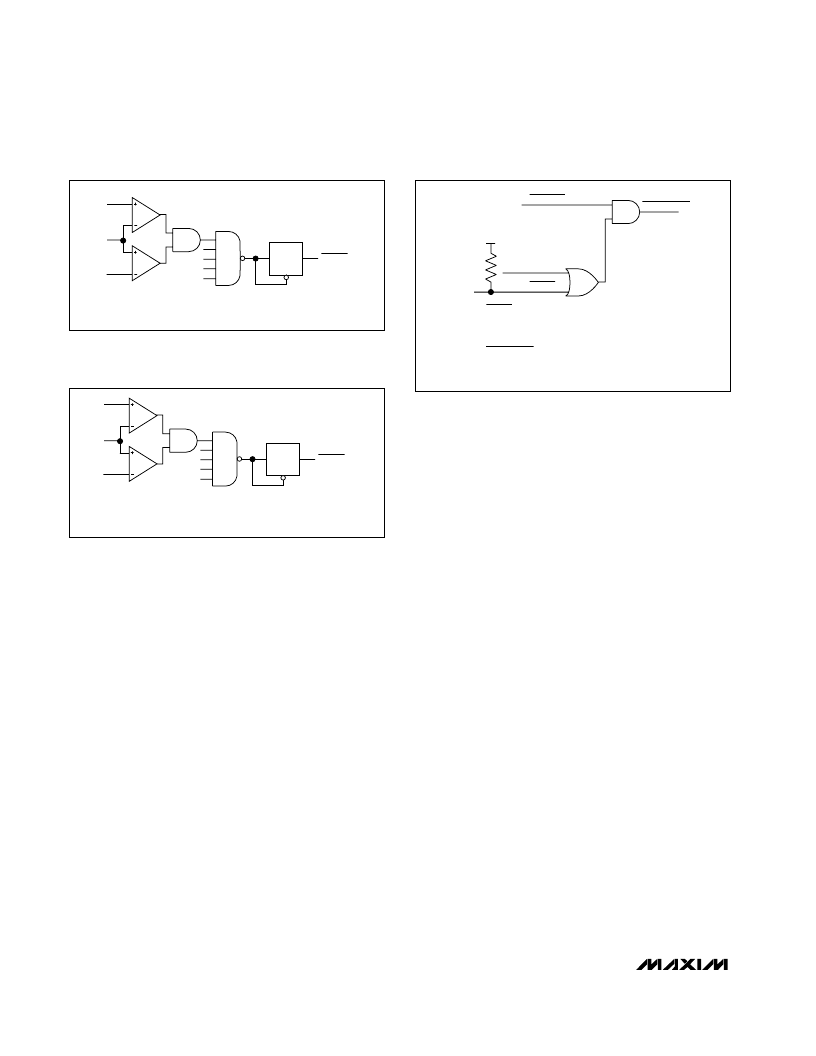
Figure 2a. MAX323_E Entering 1μA Supply Mode with
AutoShutdown
+0.3V
-0.3V
INVALID
TO MAX323 _E
POWER SUPPLY
AND TRANSMITTERS
R_IN
TRANSMITTERS ARE DISABLED, REDUCING SUPPLY CURRENT TO 1
μ
A IF
ALL RECEIVER INPUTS ARE BETWEEN +0.3V AND -0.3V FOR
AT LEAST
30
μ
s.
30
μ
s
COUNTER
R
Figure 2b. MAX323_E with Transmitters Enabled Using
AutoShutdown
+2.7V
-2.7V
INVALID
TO MAX323 _E
POWER SUPPLY
R_IN
TRANSMITTERS ARE ENABLED IF:
ANY RECEIVER INPUT IS GREATER THAN +2.7V OR LESS THAN -2.7V.
ANY RECEIVER INPUT HAS BEEN BETWEEN +0.3V AND -0.3V FOR
LESS THAN
30
μ
s.
30
μ
s
COUNTER
R
Figure 2c. MAX323_E AutoShutdown Logic
FORCEOFF
POWER DOWN
INVALID
FORCEON
INVALID IS AN INTERNALLY GENERATED SIGNAL
THAT IS USED BY THE AutoShutdown LOGIC
AND APPEARS AS AN OUTPUT OF THE DEVICE.
POWER DOWN IS ONLY AN INTERNAL SIGNAL.
IT CONTROLS THE OPERATIONAL STATUS OF
THE TRANSMITTERS AND THE POWER SUPPLIES.
V
CC
相關(guān)PDF資料 |
PDF描述 |
|---|---|
| MAX3231EEBV-T | 5V High-Speed RS-232 Transceivers with 0.1uF Capacitors |
| MAX3231E | 5V High-Speed RS-232 Transceivers with 0.1uF Capacitors |
| MAX3230EEBV-T | 5V High-Speed RS-232 Transceivers with 0.1uF Capacitors |
| MAX3232CPE | 5V High-Speed RS-232 Transceivers with 0.1uF Capacitors |
| MAX3222E-MAX3246E | 5V High-Speed RS-232 Transceivers with 0.1uF Capacitors |
相關(guān)代理商/技術(shù)參數(shù) |
參數(shù)描述 |
|---|---|
| MAX3230EBV | 制造商:Maxim Integrated Products 功能描述:+/- 15KV ESD-PROTECTED +2.5V TO +5. - Rail/Tube |
| MAX3230EBV-T | 制造商:Maxim Integrated Products 功能描述:+/- 15KV ESD-PROTECTED +2.5V TO +5.5V RS-232 - Tape and Reel |
| MAX3230EEBV | 制造商:Maxim Integrated Products 功能描述:+/- 15KV ESD-PROTECTED +2.5V TO +5. - Rail/Tube |
| MAX3230EEBV-T | 制造商:Maxim Integrated Products 功能描述:+/- 15KV ESD-PROTECTED +2.5V TO +5.5V RS-232 - Tape and Reel |
| MAX3231AEEWV+ | 制造商:Maxim Integrated Products 功能描述:+/- 15KV ESD-PROTECTED +2.5V TO +5. - Bulk |
發(fā)布緊急采購,3分鐘左右您將得到回復(fù)。